Analog Controls and Settings
Analog Input Section
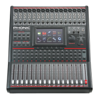
1. XLR Mic Inputs
These XLR microphone inputs can be
used in conjunction with a wide range
of microphones, such as professional
condenser, dynamic or ribbon microphones,
with standard XLR male connectors.
With seriously low-noise preamplifiers,
these inputs serve for crystal clear sound
replication.
NB. When using an unbalanced microphone, it’s
best to ensure that phantom power is switched
off. However, when using condenser microphones
the phantom power should be activated. Check
your microphone’s user manual for information on
whether to use phantom power or not.
2. 1/4” Line Inputs
These 1/4” TRS phone jack inputs accept signals from both
balanced and unbalanced line-level sources. Channels 1 through
16 all feature a single line input jack. It should be noted that
phantom power is not fed to these inputs.
3. Insert Jacks
This 1/4” TRS phone jack can be used in conjunction with a split- or
y-cable to allow an external device (effects processor, compressor,
etc) to be used in conjunction with the corresponding channel’s
signal. The TRS jack’s tip will send the signals to the external
device, while the ring will receive the return signal back to the
mixer. The sleeve acts as the grounding.
4. PAD Switch
Pushing the PAD switch in will attenuate the signal of the
corresponding channel 20 dB. The PAD button can be found on
channels 1 through 16.
5. Gain Control
The Gain control allows users to adjust the input sensitivity of the
corresponding input. Line level signals can be adjusted between
-10 and 40 dB (when the PAD button is engaged), whereas mic
signals can be adjusted between 10 and 60 dB (when the PAD
button is released).
6. Peak Indicator
This LED indicator will light up when the corresponding channel
reaches 0 dB on the respective channels meter.
Monitoring & Headphones
7. Phones Output
This 1/4” TRS phone jack is for sending stereo signals to a pair
of headphones, allowing signals to be monitored.
8. Phones Control
This control will adjust the level of the Phones Output.
9. Control Room Rotary Control
This control will adjust the signal level of the Control Room outputs,
found on the rear of the SUMMIT.
2 Track Send and Return
10. Channel 15/16 / 2TR In Button
This button changes the input source of input channels 15 and
16. Pushing it in will allow channels 15 and 16 to use the signal
taken from the RCA 2TR inputs found on the rear of the SUMMIT.
When this button is disengaged, the XLR or 1/4” line input jacks
will be used for these input channels.
11. Control Room / 2TR In Button
Pushing this button in allows users to monitor the RCA 2TR inputs
through the Control Room outputs. When released, users will be
able to monitor their main stereo signal or Solo signals.
Channel Strips
12. Select Button
This button allows you to select the current channel. Which
channel is selected (either the input channel or the corresponding
AUX, Group or Multi mix), will depend on your layer settings. The
Main channel strip also features a select button, allowing users to
adjust the properties of the Main mix.
13. Solo Button
Push this button to ‘solo’ the corresponding channel, sending it to
the Control Room mix. The Solo indicator within the button will
light up when a Solo is activated on a channel.
14. On Button
These buttons will activate the current channel. Activation will be
accompanied by an illuminated LED within the button.
15. Faders
These faders will adjust the level of the currently
selected Channel / AUX / Group / Main mix. They are
completely automated, so will revert to their appropriate
positions when layer settings are altered. They will also
automatically adjust their position when virtual faders
are altered through the GUI.
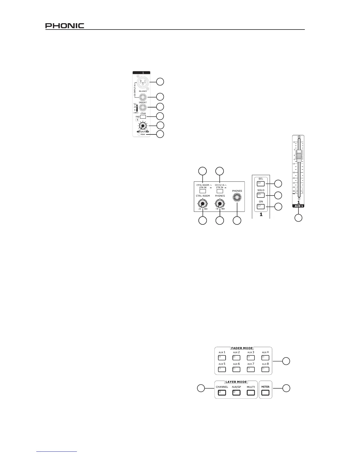
Mode Buttons
16. AUX (Sends) Fader Mode Buttons
Any one of these AUX buttons (from 1 to 8) will allow users to
assign AUX send on to channel faders. This will allow you to
adjust the signals sent from each input channel to the selected
AUX mix.
17. Layer Mode Buttons
These three buttons determine which signals the channel strips
will control. When “CHANNEL” is selected, the channel strips will
control the main input signals (channels 1 through 16), whereas
if “AUX/GP” is selected, the channel strips will control the AUX
1 to 8 and Group 1 to 8 mixes. When “MULTI” is selected the
channels strips will control the AES/EBU In, Effect 1 and 2, and
Multi 1 through 8. The CHANNEL and AUX/GP buttons both have
an LED that indicates when the layer is selected (not featured on
the MULTI button).
18. Meter Button
The Meter button allows users to jump immediately to the meter
function in the LCD display’s GUI.