7SUMMIT
Display
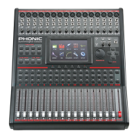
19. LCD Touch Screen
This color LCD touch screen allows users to view and access
various functions on the SUMMIT.
20. Function Buttons
These buttons allow users to skip directly to another page/tab of
options on the onscreen display. There may be any number of
pages/tabs available on any given function of the SUMMIT. While
the on-screen display can be used to jump directly to these tabs/
pages, these buttons are available for users who prefer hardware
buttons, or just want to use them for one or another reason.
21. Up and Down Buttons
These buttons will help users scroll or run through all of the
available functions of the SUMMIT, the icons of which can be
found on the top right-hand site of the GUI.
22. FireWire / USB Indicators
These LED indicators will illuminate when a connection is
established through either the USB 2.0 or FireWire connection.
The FireWire + USB 2.0 Expansion Card will need to be installed
for this to be possible, however.
Control Section
23. Jog Wheel
This jog wheel is used when adjusting any parameter within the
GUI software. Turning the control clockwise will increase the
value of the parameter, while turning it counterclockwise will
decrease the value.
35
34
24. Enter Button
This button is used to select the currently highlighted property or
to conrm edited values within the GUI software. The Enter button
can also be used when adjusting tap delay time when the Tap Delay
effect is selected. In addition to this, the Enter button will allow
users to adjust AUX sends between pre- and post-fader sends
by pushing and holding it down and selecting the corresponding
virtual onscreen control.
25. Directional Buttons
These buttons are used to move through the menu on the GUI.
Users can scroll through the various parameter controls and faders
within each individual function menu.
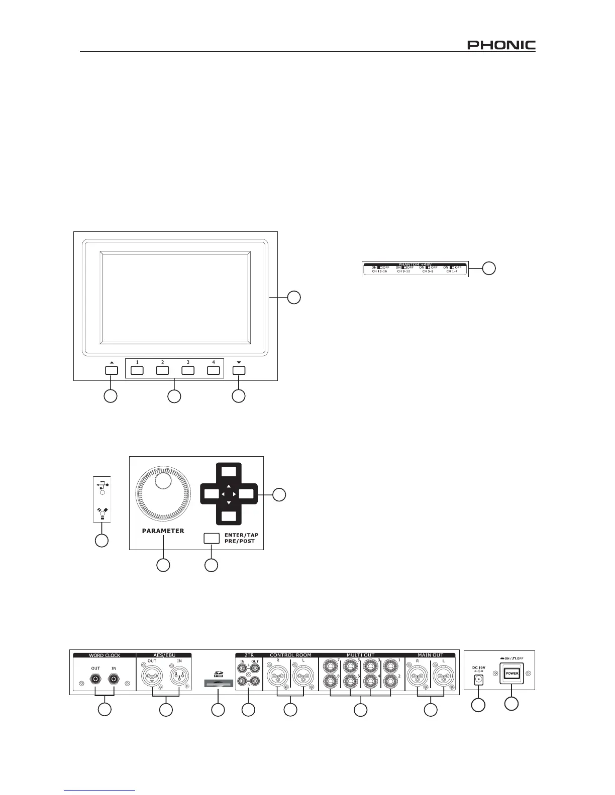
Rear Panel
26. Phantom Power Switches
These grouped phantom power switches allow users to activate
+48V of to feed the Microphone inputs. Phantom Power is grouped
as follows: channels 1 through 4, 5 through 8, 9 through 12 and
13 through 16.
27. Main Outputs
These balanced XLR outputs are for sending the Main Left and
Right signal of the SUMMIT out to external devices.
28. Multi Outputs
These balanced 1/4” TRS phone jack outputs are for sending any
of the input signals or other bus signals out to external devices.
The signal sources of these multi outputs are decided through the
onboard control software.
29. Control Room Outputs
These balanced 1/4” TRS phone jacks are for sending the monitor
signals to external devices such as active monitors. These jacks
can also output the 2TR input signal, depending on the selection
of the Control Room / 2TR In button.
30. Stereo 2TR Inputs and Outputs
These stereo RCA inputs and outputs are for sending and receiving
signals to and from consumer-level audio devices such as CD
players, MP3 players and the like. The 2T Input signal can be
assigned to channels 15 and 16 or the Control Room as required,
and the Outputs are taken directly from the Main stereo mix.
31. SD Card Slot
The SD card slot is used for saving and loading presets, as
well as updating the SUMMIT’s rmware. Firmware updates
are accomplished by inserting an SD Card and selecting the
appropriate Firmware update option in the Setup menu of the
GUI.
32. AES/EBU In & Out
These connectors accept and send digital signals from AES/EBU-
enabled devices. The AES/EBU input can be assigned to the Main
mix by pushing the AES/EBU button within the GUI software, while
the main signal will be sent to the AES/EBU output.
33. Word Clock In & Out
These BNC connectors send and receive word clock signals to
and from external devices.
34. Power Button
Use this button to turn the SUMMIT on and off.