User Manual
E712T0010, valid for E-712.N1, E-712.1AM, E-712.1AN, .2AN, .3AN
CMo, BRo, 10/31/2024
Physik Instrumente (PI) SE & Co. KG, Auf der Römerstraße 1, 76228 Karlsruhe, Germany page 5 / 40
Phone +49 721 4846-0, fax +49 721 4846-1019, e-mail info@pi.ws, www.pi.ws
For stepping motion, a step cycle is defined as a complete piezo-voltage-changing sequence for shearing and
clamping. At the end of the step cycle, the piezo voltages show the same values in the same relation as at the
start of the step cycle.
The step size of a PiezoWalk® drive depends on the load and the resulting force. Depending on the direction of
motion the drive acts against that force or in the direction of that force. Accordingly, the actual steps size varies.
Furthermore, the displacement of the piezo actuators of the piezo drive modules is not linear due to hysteresis.
For that reason, the stepping motion of PiezoWalk® drives is not comparable to the feed provided by classical
stepper motors. To make a clearer distinction between them, the stepping motion of PiezoWalk® drives is
therefore also referred to as “walking motion”.
For applications requiring repeatable and high-precision positioning it is therefore recommended to use a
position sensor (e.g. high-resolution incremental sensors).
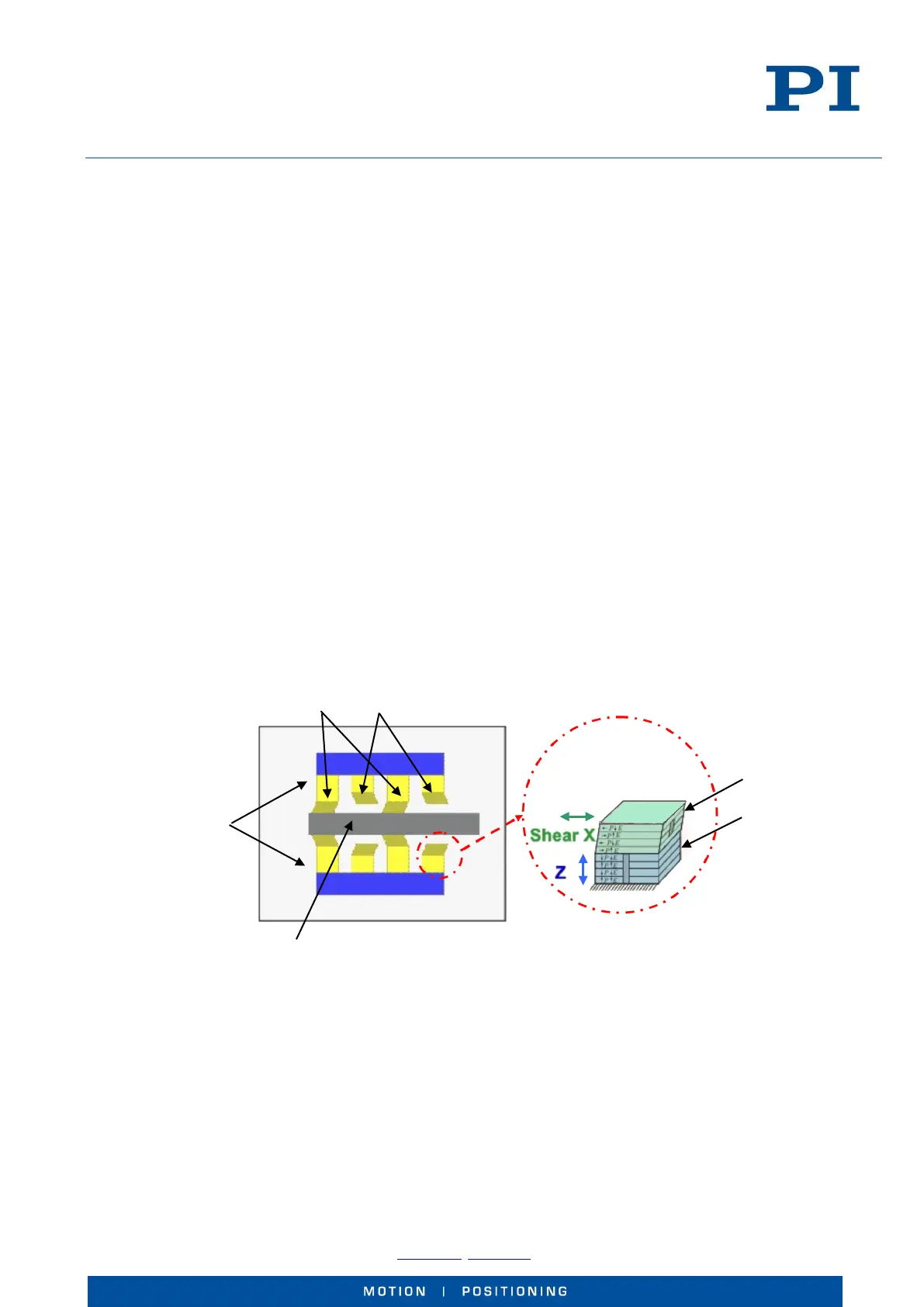
3.1 Special Characteristics of NEXLINE® Drives
A NEXLINE® piezo drive module consists of multiple NEXLINE® stack actuators. Each of these actuators consists of
a clamping segment and a shearing segment.
The NEXLINE® stack actuators require a piezo voltage in the range of -250 to +250 V.
NEXLINE® stack actuator pairs of one piezo drive module:
NEXLINE®
piezo drive
modules
actuator details:
Shearing segment
(“D”)
Clamping
segment („C“)
Runner
Fig. 2: NEXLINE
®
drive with 2 piezo drive modules, performing