© 2022 Pierce Manufacturing Inc. All Rights Reserved. Husky 3 Foam System / 2-11
GENERAL
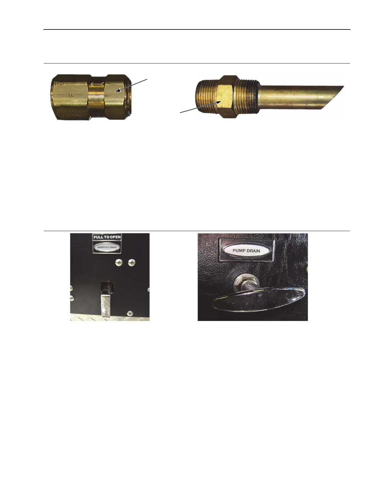
2-2.2h Foam Injection Check Valve
Figure 2-13: Foam Injection Check Valve
1354, 1355
The Foam Injection Check Valve located in the foam discharge line prevents water from flowing backwards through
the foam system and contaminating the foam supply.
2-2.3 Water Supply System
The water supply system supplies water to the foam injection manifold for foam to be added and distributed to the
foam/water discharges. This system consists of an in-line water check valve, water flowmeter and flowmeter
installation tee. The size of the check valve and the flowmeter installation tee are dependent on the water flow rates
and the number of foam/water discharges in the system.
2-2.3a Manifold and Master Drains
Figure 2-14: Manifold & Master Drains
1325, 1067
The manifold drains are used to bleed off pressure/water anytime the water pump has been pressurized (after the
water pump is shut off). If a dry water pump condition is desired, leave manifold drains open until the fire scene is
reached.
The master pump drain will empty both the discharge and inlet manifolds of water when opened. The water pump
drain should be pulled (opened) daily.
Foam Injection
Check Valve
Foam Injection
Fitting