© 2022 Pierce Manufacturing Inc. All Rights Reserved. Husky 3 Foam System / 2-13
GENERAL
2-2.4a Control Head
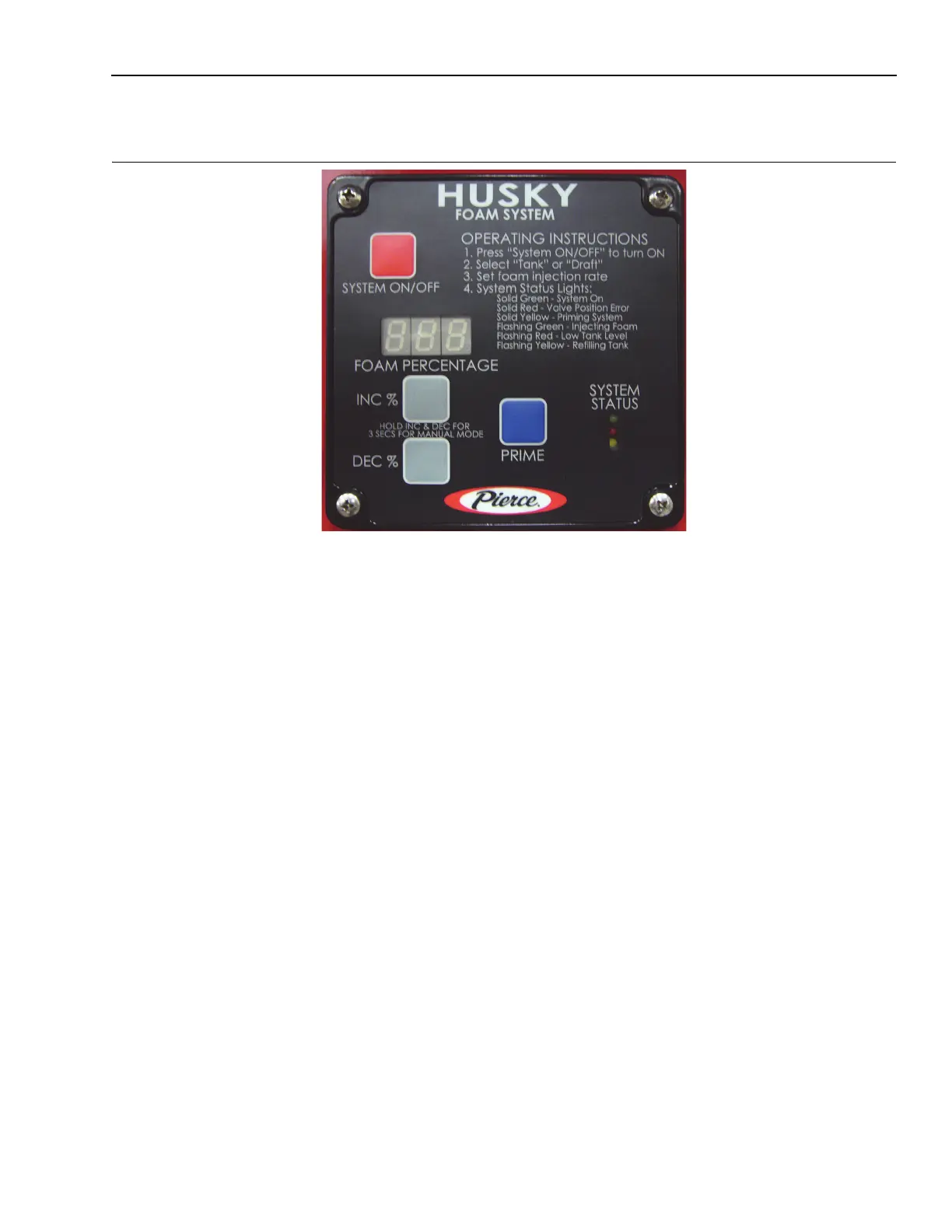
Figure 2-17: Control Head
1311
The Foam System Control Head is the operator interface with the foam system. It is located on the main pump
panel. It has four operating buttons: System On/Off, Prime, INC %, and DEC %. The display is a 3 character LED
screen. System power is indicated by the display showing the default % setting IE 0.5; the foam system ON is
indicated by a solid green LED.
Information displayed on the LED screen includes: mode of operation and various information displays. If the foam
system is turned OFF, the display will show the last setting or default % setting.
The percent of injection has presets for class A foam. The preset can be changed at the fire department as desired.
The percent of injection can be easily changed at the scene to adjust for changing demands.
The modes of operation are: Onboard Tank, Draft, Tank Fill, Manual Mode and Set Up. Pressing the INC % or
DEC % buttons and/or changing the position of one or both of the two way valves (Tank/Draft valve or Injection/Fill
valve). (Detailed instructions on the operation of each mode can be found in Section 3, “Operation”.)
The foam system is controlled by a foam system controller module which is intergrated into the Foam System
Control Head. This contains the programming to actuate the appropriate valves, direct the hydraulic fluid, and control
the injection rate of the foam. All components plug into the foam system controller module. The foam module is what
actually controls the system. The user interfaces with the controller through the foam system control head. If
replaced, the system calibration must be checked.
 Loading...