MAINTENANCE
4-8 / Husky 3 Foam System
© 2022 Pierce Manufacturing Inc. All Rights Reserved.
9. Pump stalls with power unit
running.
Incorrect hydraulic system
pressure.
• Install pressure gauge on the
GP pressure port and confirm
pressure setting is 2000 PSI.
See “Checking Hydraulic
System Pressure” on page 4-5.
Foam Pump (LVDT) Transducer
feedback voltage not correct.
-low set range is 0.55 to .75 volts
-high set range is 4.40 to 4.20 volts
• Confirm feed back voltage
range in calibration mode
(screen C7). See “Configuration
Procedure” on page 4-2.
Foam Pump (LVDT) Transducer not
calibrated.
• Auto-Calibrate Foam Pump
(LVDT) Transducer (screen
C7). See “Configuration
Procedure” on page 4-2.
Incorrect voltage at proportional
valve.
• Confirm 12 vdc at proportional
valve.
10. System runs but doesn't make
capacity.
No foam concentrate. • Check foam tank level. Fill if
required.
Inlet strainer plugged. • Check inlet strainer for
obstructions.
Vacuum leak. • Check inlet hose and/or inlet
connections for vacuum leak.
Vacuum leak. • Install vacuum gauge on inlet
and confirm vacuum level
(20hg).
Insufficient voltage to power unit. • Confirm truck voltage at the
power unit is 13.4 volts.
Incorrect hydraulic system
pressure.
• Install pressure gauge on the
GP pressure port and confirm
pressure setting is 2000 PSI.
See “Checking Hydraulic
System Pressure” on page 4-5.
Foam Pump (LVDT) Transducer
feedback voltage not correct.
-low set range is 0.55 to .75 volts
-high set range is 4.40 to 4.20 volts
• Confirm feed back voltage
range in calibration mode
(screen C7). See “Configuration
Procedure” on page 4-2.
Foam Pump (LVDT) Transducer not
calibrated.
• Auto-Calibrate Foam Pump
(LVDT) Transducer (screen
C7). See “Configuration
Procedure” on page 4-2.
Foam Pump Inlet and Outlet Check
Valves (four) not sealing properly
• Remove Inlet and Outlet
Manifolds and inspect the
Check Valves and O-Rings for
damage.
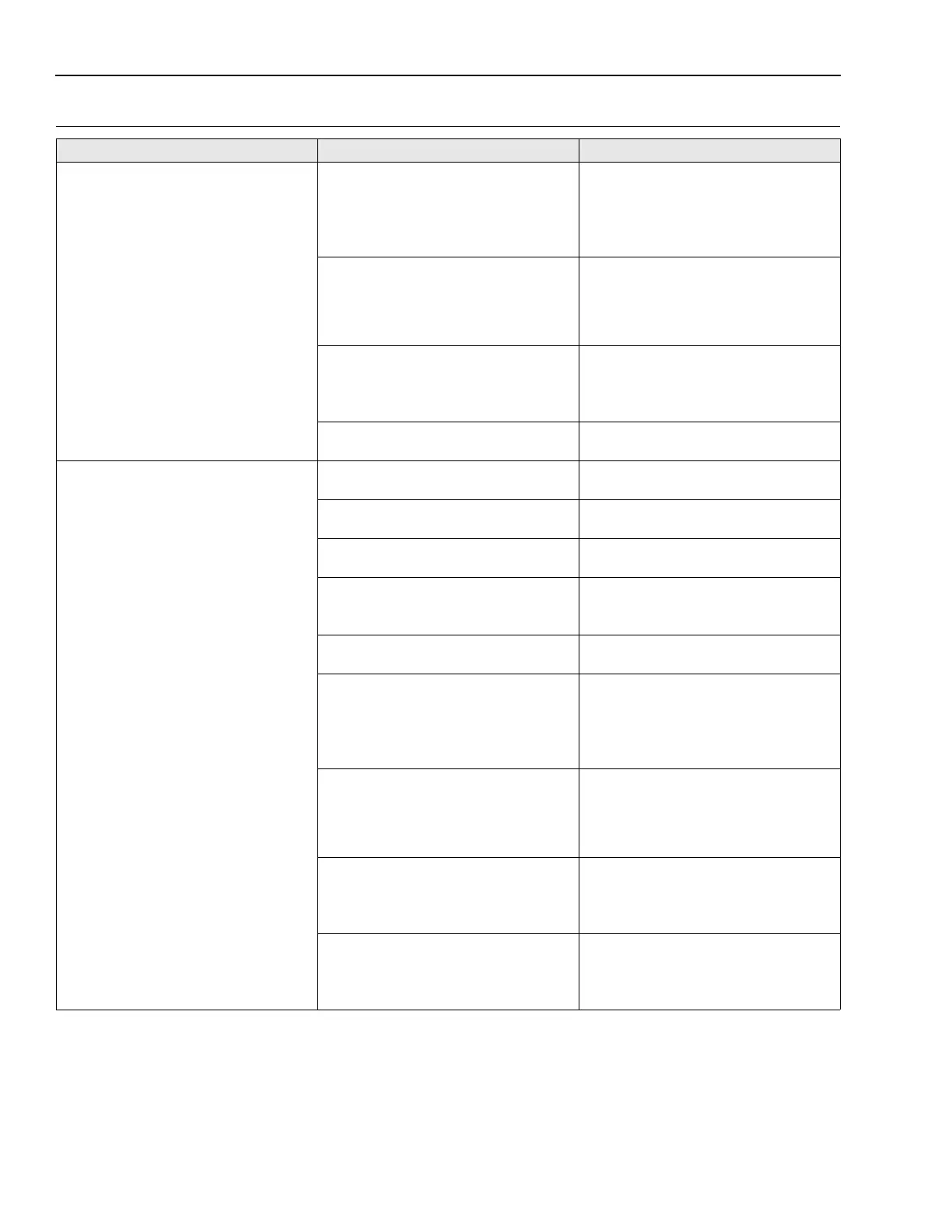
Table 4-3: General Troubleshooting
Symptom Possible Cause Corrective Action
 Loading...