Component Maintenance Manual
EFFECTIVITY: ALL
21-00-22
Page 2001
JULY 21, 2011
SCHEMATIC AND WIRING DIAGRAMS
21-00-22-99-801
4.0 R12 AIR CONDITIONING SYSTEM SCHEMATI
C AND WIRING DIAGRAMS
SUBTASK 21-00-22-99-001
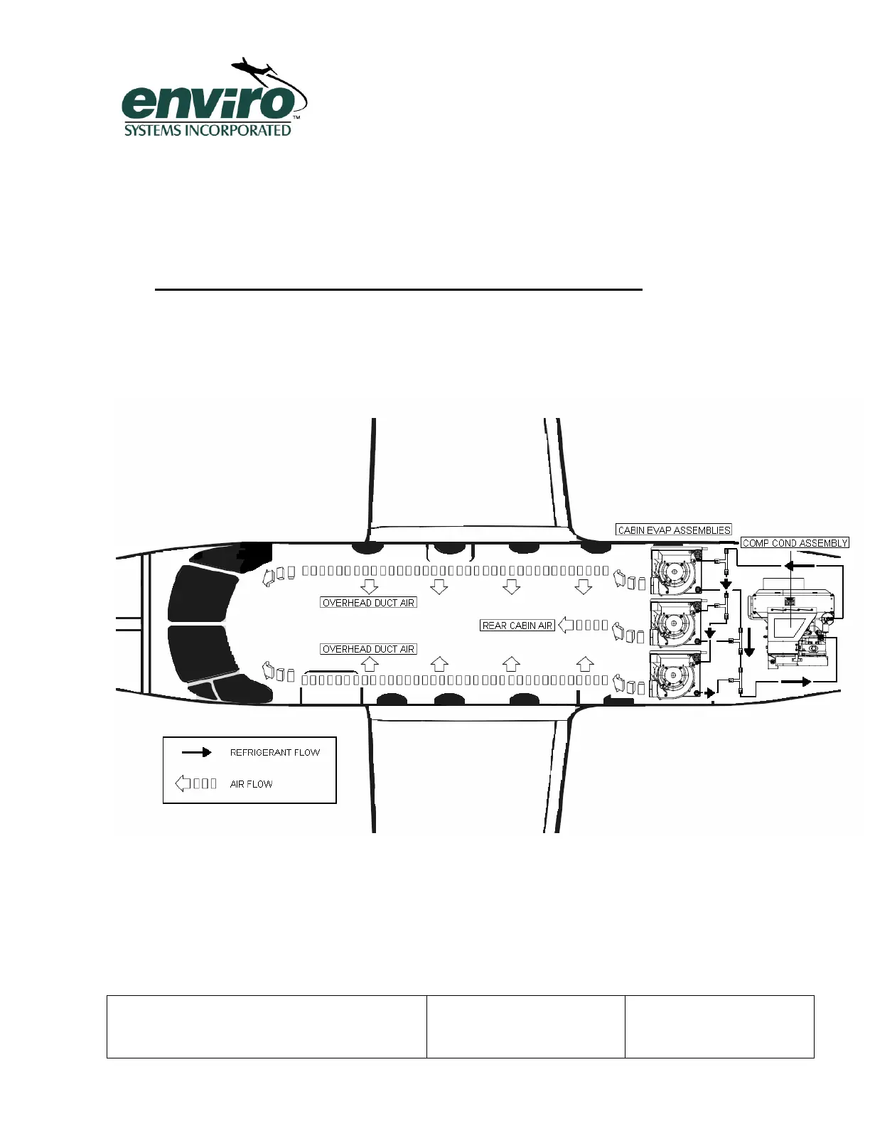
4.1 R12 Refrigerant Flow Schematic:
4.1.1 The followi
ng schematic shows an air conditioning system and its associated components
as well as the flow of the R12 refrigerant.
Figure 2 R12 Refrigerant Flow Schematic