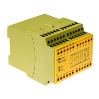
P2HZ X1
Operating Manual P2HZ X1
20124-EN-09
| 12
Installation
} The unit should be installed in a control cabinet with a protection type of at least IP54.
} Use the notch on the rear of the unit to attach it to a DIN rail (35 mm).
} When installed vertically: Secure the unit by using a fixing element (e.g. retaining bracket
or end angle).
WARNING!
Loss of the safety function due to too short distance of the operator
elements to the hazardous area!
The distance of the two-hand control relay to the nearest hazardous area
must be large enough so that if one of the operator elements is released,
the hazardous movement is interrupted before the operator reaches the
hazardous area or can reach into the hazardous area. You must maintain
the minimum distance in accordance with EN ISO 13855.
Depending on the application, serious injury or death may result.
Wiring
Please note:
} Information given in the "Technical details [ 20]" must be followed.
} Outputs 13-14, 23-24, 33-34 are safety contacts; output 41-42 is an auxiliary contact (e.g.
for display).
} Do not use auxiliary contacts 41-42 and semiconductor outputs Y32 and Y35 for safety
circuits!
} Do not connect undesignated terminals.
} To prevent contact welding, a fuse should be connected before the output contacts (see
Technical details [ 20]).
} Calculation of the max. cable length l
max
in the input circuit:
R
lmax
= max. overall cable resistance (see Technical details [ 20])
R
l
/km = cable resistance/km
} Use copper wiring with a temperature stability of 60/75 °C.
} To prevent EMC interferences (particularly common-mode interferences) the measures
described in EN60204-1 must be executed. This includes the separate routing of cables
of the control circuits (input, start and feedback loop) from other cables for energy trans-
mission or the shielding of cables, for example.
} The supply voltage must be switched off with the operating energy of the machine.
} Only contactors with positive-guided contacts should be used for safety functions.
} Adequate protection circuit must be provided on all output contacts with capacitive and in-
ductive loads.
} Do not switch low currents using contacts that have been used previously with high cur-
rents.

 Loading...