PNOZ s7.1
Operating Manual PNOZ s7.1
21865-EN-11
| 12
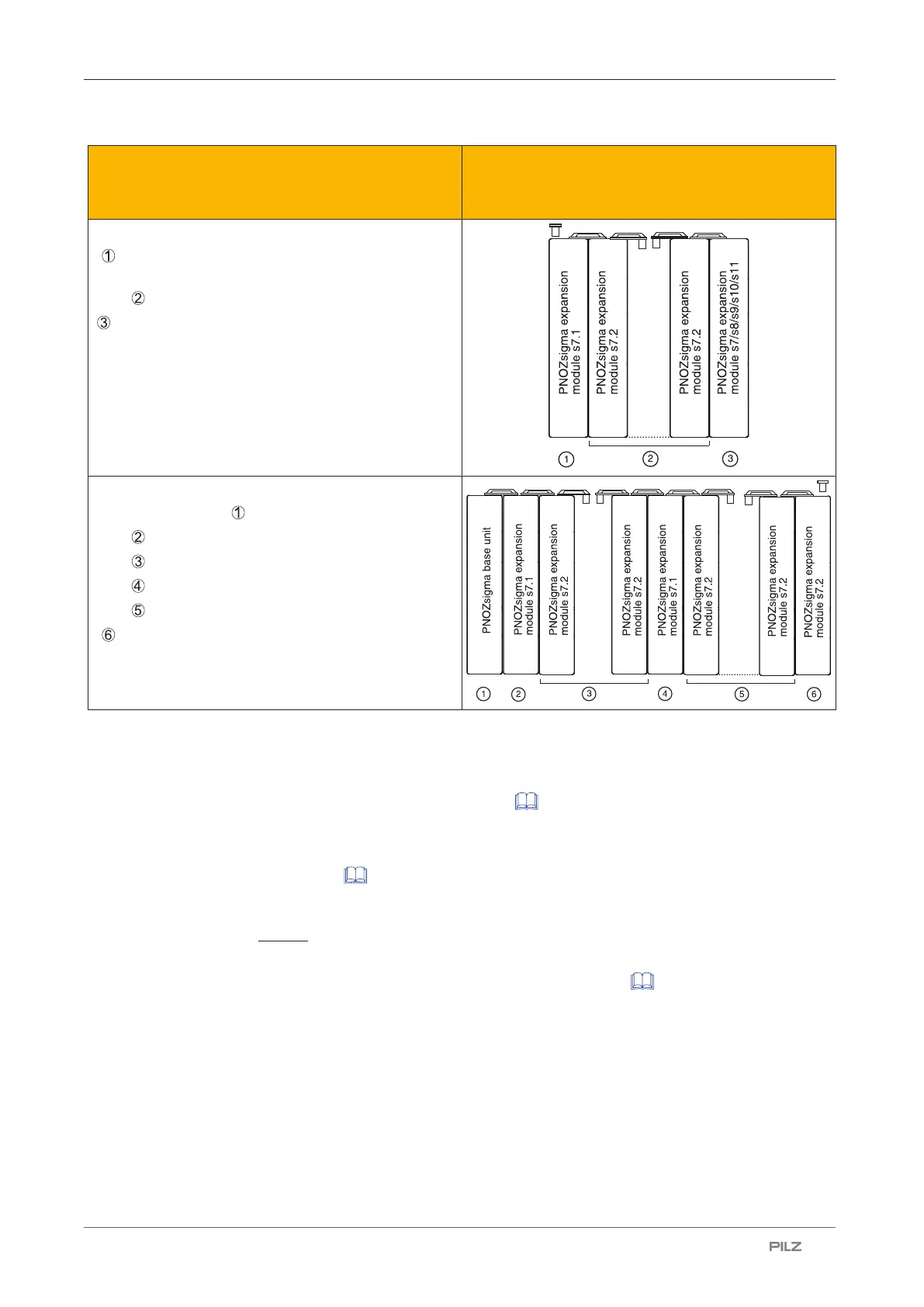
Expansion options Please note the max. power consumption of the
contact expansion modules (see technical data
PNOZs7.1).
: Contact expansion module PNOZs7.1 with ter-
minator
: Contact expansion module PNOZs7.2
: Expansion module PNOZ s7, s8, s9, s10, s11 as
a terminator
: Base unit
: Contact expansion module PNOZs7.1
: Contact expansion module PNOZs7.2
: Contact expansion module PNOZs7.1
: Contact expansion module PNOZs7.2
: Contact expansion module PNOZs7.2 with ter-
minator
Wiring
Please note:
} Information given in the "Technical details [ 17]" must be followed.
} The output contacts 13-14, 23-24, 33-34 are safety contacts.
} To prevent contact welding, a fuse should be connected before the output contacts (see
Technical details [ 17]).
} Calculation of the max. cable length l
max
in the input circuit:
R
lmax
= max. overall cable resistance (see Technical details [ 17])
R
l
/km = cable resistance/km
} Use copper wiring with a temperature stability of 75 °C.
} To prevent EMC interferences (particularly common-mode interferences) the measures
described in EN60204-1 must be executed. This includes the separate routing of cables
of the control circuits (input, start and feedback loop) from other cables for energy trans-
mission or the shielding of cables, for example.
} Adequate protection must be provided on all output contacts with capacitive and inductive
loads.

 Loading...


