- 4 -
Mise en oeuvre :
• Tension d’alimentation
- AC: amener la tension d’alimentation sur
A1 et A2; relier la borne terre
- DC: amener la tension d’alimentation sur
B1 et B2
• Circuit de réarmement:
- réarmement automatique: pontage des
bornes S13-S14
- réarmement manuel auto-côntrolé:
câblage d'un poussoir sur S33-S34
(S13-S14 ouvert).
• Circuits d’entrée:
- Commande par 1 canal : câblage du
contact à ouverture entre S11-S12,
pontage entre S21-S22 et S31-S32
- Commande par 2 canaux: câblage des
contacts à ouverture entre S21-S22 et
S31-S32, pontage entre S11-S12
• Boucle de retour:
câbler les contacts des contacteurs
externes en série dans le circuit de
réarmement S13-S14 ou S33-S34
• Alimentation 24 V DC de la sortie statique:
relier le +24 V DC à la borne Y31 et le 0 V
à la borne B2, relier également le 0 V de
l'API à B2.
Les contacts de sécurité se ferment et le
contact d’information 41-42 s’ouvre. Les
LEDs "CH.1", "CH.2" et "OUT" sont
allumées. L’appareil est prêt à fonctionner.
Si le circuit d’entrée est ouvert, les contacts
de sécurité retombent et le contact
d’information 41-42 se ferme. Les LEDs
s’éteignent.
Remise en route :
• fermer le circuit d’entrée
• en cas de surveillance du circuit de
réarmement, appuyer le poussoir de
validation S33-S34.
Les affichages d'état s'allument à nouveau.
Les contacts de sécurité sont fermées.
Utilisation
Les figures 2 à 10 représentent les différents
câblages possibles du PNOZ X3.1 à savoir :
poussoir AU avec réarmement automatique
ou auto-côntrolé, interrupteurs de position et
augmentation du nombre des contacts de
sécurité par contacteurs externes.
• Fig. 2 et 7: pas de câblage sur S33-S34.
L’appareil se réarme automatiquement
après une coupure et une remise sous
tension. Evitez tout risque de redémarrage
par un câblage externe approprié.
• Fig. 3, 4 et 5, 6:
pas de câblage sur S13-S14
• Fig. 7: Réarmement automatique en cas
de surveillance protecteur: lorsque le
protecteur est ouvert, le circuit S13-S14
se ferme et le relais est prêt à fonctionner.
Dès la fermeture des canaux d'entrée
S11-S12, S21-S22 et S31-S32, les
contacts de sortie du relais se ferment.
To operate:
• Supply operating voltage
- AC: Connect the operating voltage to
terminals A1 and A2; connect the
operating earth terminal with the ground
earth.
- DC: Connect the terminals B1 and B2
with the operating voltage.
• Reset circuit:
- Automatic reset: Bridge S13-S14
- Manual reset with monitoring: Connect
button to S33-S34 (S13-S14 open).
• Input circuit:
- Single-channel: Bridge S21-S22 and
S31-S32. Connect N/C contact from
safety switch (e.g. Emergency-Stop) to
S12 and S11.
- Two-channel: Bridge S11-S12. Connect
N/C contact from safety switch (e.g.
Emergency-Stop) to S21-S22 and S31-
S32.
• Feedback control loop:
Connect external relays/contactors in
series to reset circuit S13-S14 or S33-S34
• 24 VDC supply voltage for semi-conductor
output: Connect +24 V DC to terminals
Y31 and 0 V DC to B2,
additionally
connect 0 V of the PLC to B2.
The safety contacts are activated (closed)
and the auxiliary contact (41-42) is open.
The status indicators "CH.1 IN", "CH.2 IN"
and "OUT" are illuminated. The unit is ready
for operation. If the input circuit is opened,
the safety contacts 13-14/23-24, 33-34 open
and the auxiliary contact 41-42 closes. The
status indicator goes out.
Reactivation
• Close the input circuit.
• For manual reset with monitoring, press
the button between S33-S34.
The status indicators light up again, the
safety contacts are closed.
Application
In Fig. 2 ... Fig. 10 are connection examples
for Emergency Stop wiring with automatic
and monitored reset. Safety gate controls
as well as contact expansion via external
contactors.
• Fig. 2 and 7: S33-S34 not connected. The
device starts automatically after loss of
power. You should prevent an unintended
start-up by using external circuitry
measures.
• Fig 3, 4 and 5, 6: S13-S14 not connected
• Fig. 7: Automatic reset with safety gate
control: with the safety gate open the unit
is ready for operation via reset circuit
S13-S14. After closing the safety input
circuit S11-S12, S21, S22 and S31-S32
the safety contacts will close.
Ablauf:
•
Versorgungsspannung
:
- AC:
Versorgungsspannung
an Klem-
men A1 und A2 anlegen; Betriebser-
dungsklemme mit Schutzleitersystem
verbinden
- DC:
Versorgungsspannung
an
Klemmen B1 und B2 anlegen
• Startkreis:
- Automatischer Start: S13-S14 brücken.
- Manueller Start mit Überwachung:
Taster an S33-S34 anschließen (S13-
S14 offen)
• Eingangskreis:
- Einkanalig: S21-S22 und S31-S32
brücken. Öffnerkontakt von Auslöse-
element an S11 und S12 anschließen.
- Zweikanalig: S11-S12 brücken.
Öffnerkontakt von Auslöseelement an
S21-S22 und S31-S32 anschließen.
•
Rückführkreis:
Externe Schütze in Reihe zu Startkreis
S13-S14 bzw. S33-S34 anschließen.
• 24 V Versorgungsspannung für
Halbleiterausgang: +24 V DC an Klemme
Y31 und 0 V an Klemme B2 anschließen,
zusätzlich 0 V der SPS mit B2 verbinden
Die Sicherheitskontakte sind aktiviert (ge-
schlossen) und der Hilfskontakt 41-42 ist
geöffnet. Die Statusanzeigen für "CH.1 IN",
"CH. 2 IN" und "OUT", leuchten. Das Gerät
ist betriebsbereit. Wird der Eingangskreis
geöffnet, öffnen die Sicherheitskontakte
13-14/23-24/33-34 und der Hilfskontakt
41-42 schließt. Die Statusanzeige erlischt.
Wieder aktivieren
• Eingangskreis schließen.
• Bei manuellem Start mit Überwachung
Taster zwischen S33 und S34 betätigen.
Die Statusanzeigen leuchten wieder, die
Sicherheitskontakte sind geschlossen.
Anwendung
In Fig. 2 ... Fig. 10 sind Anschlussbeispiele
für Not-Halt-Beschaltung mit automatischem
und überwachtem Start, Schutztüran-
steuerungen sowie Kontaktvervielfachung
durch externe Schütze.
Bitte beachten Sie:
• Fig. 2 und 7: keine Verbindung S33-S34.
Das Gerät startet bei Spannungsausfall
und -wiederkehr automatisch. Verhindern
Sie einen unerwarteten Wiederanlauf
durch externe Schaltungsmaßnahmen.
• Fig. 3, 4 und 5, 6:
keine Verbindung S13-S14
• Fig. 7: Automatischer Start bei Schutztür-
steuerung: Das Gerät ist bei geöffneter
Schutztür über den Startkreis S13-S14
startbereit. Nach Schließen der Eingangs-
kreise S11-S12, S21-S22 und S31-S32
werden die Sicherheitskontakte geschlos-
sen.
S21
S22
S12
S34
S32
S33
S11
S31
S1
S3
S11 S31
S13
S12
S14
S32
S21
S22
S1
S11 S31
S33
S12
S34
S32
S21
S22
S1
S3
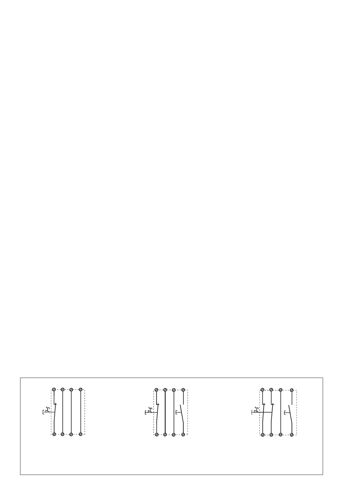
Fig. 4: Eingangskreis zweikanalig, über-
wachter Start/Two-channel input circuit,
monitored reset/Commande par 2 canaux,
surveillance du poussoir de validation
Fig. 3: Eingangskreis einkanalig, überwach-
ter Start/Single-channel input circuit,
monitored reset/Commande par 1 canal,
surveillance du poussoir de validation
Fig. 2: Eingangskreis einkanalig, automat.
Start/Single-channel input circuit, automatic
reset/Commande par 1 canal, validation
automatique

 Loading...