PSEN cs1.1p
Operating Manual PSEN cs1.1p
21095-EN-10
10
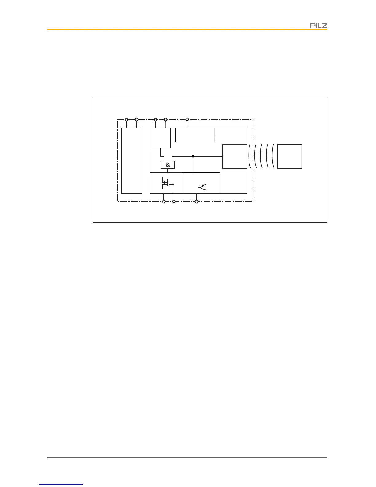
} Signal output/diagnostic output Y32
The status of the actuator is output. If a fieldbus module of the SDD is used, the signal
output/diagnostic output for the writing of data is activated.
Block diagram
Safety Device Diagnostics
Safety Device Diagnostics is an option that can be selected independently of the safety-re-
lated wiring.
When using the Safety Device Diagnostics, up to 16 sensors connected in series can be
connected as a subscriber to a fieldbus module.
The communication of the sensors with the fieldbus module is automatically built up again
with each new supply of the supply voltage. As a result, a sensor can be exchanged, e.g.
when servicing, without the need for special measures.
An exchange can be detected via the fieldbus module e.g. through the serial number.
} With Safety Device Diagnostics there are the following diagnostic options for the field-
bus module:
– Poll information of the sensors (examples: what sensor in the series has switched,
at what point could there be an open circuit in the series connection)
– Read configuration parameters of the sensors (examples: Number of remaining
teach-in processes, serial number of the switch)
– Perform actions (example: poll updated actuator name)
The results of the sensor diagnostics can be checked already during the installation phase
via the display in the fieldbus module, without the need to connect the fieldbus module to
the network.
} With Safety Device Diagnostics there are the following diagnostic options for the field-
bus module for simple wiring:
– Information is passed on via the fieldbus module directly to the network

 Loading...


