PSEN cs1.1p
Operating Manual PSEN cs1.1p
21095-EN-10
9
– Manipulation protection in accordance with ISO 14119 (chap. 7.2.d) is possible by
verifying the short name of the actuator through the controller via SDD communica-
tion
} Diagnostic input for Y1 for Safety Device Diagnostics (SDD)
} Signal output/diagnostic output Y32 for Safety Device Diagnostics
} LED display for:
– State of the actuator
– State of the inputs
– Supply voltage/fault
} 4 directions of actuation
Function description
The safety outputs may have a high or low signal, depending on the position of the actuator
and the signal status of the inputs.
In a safe condition there is a low signal at the safety outputs.
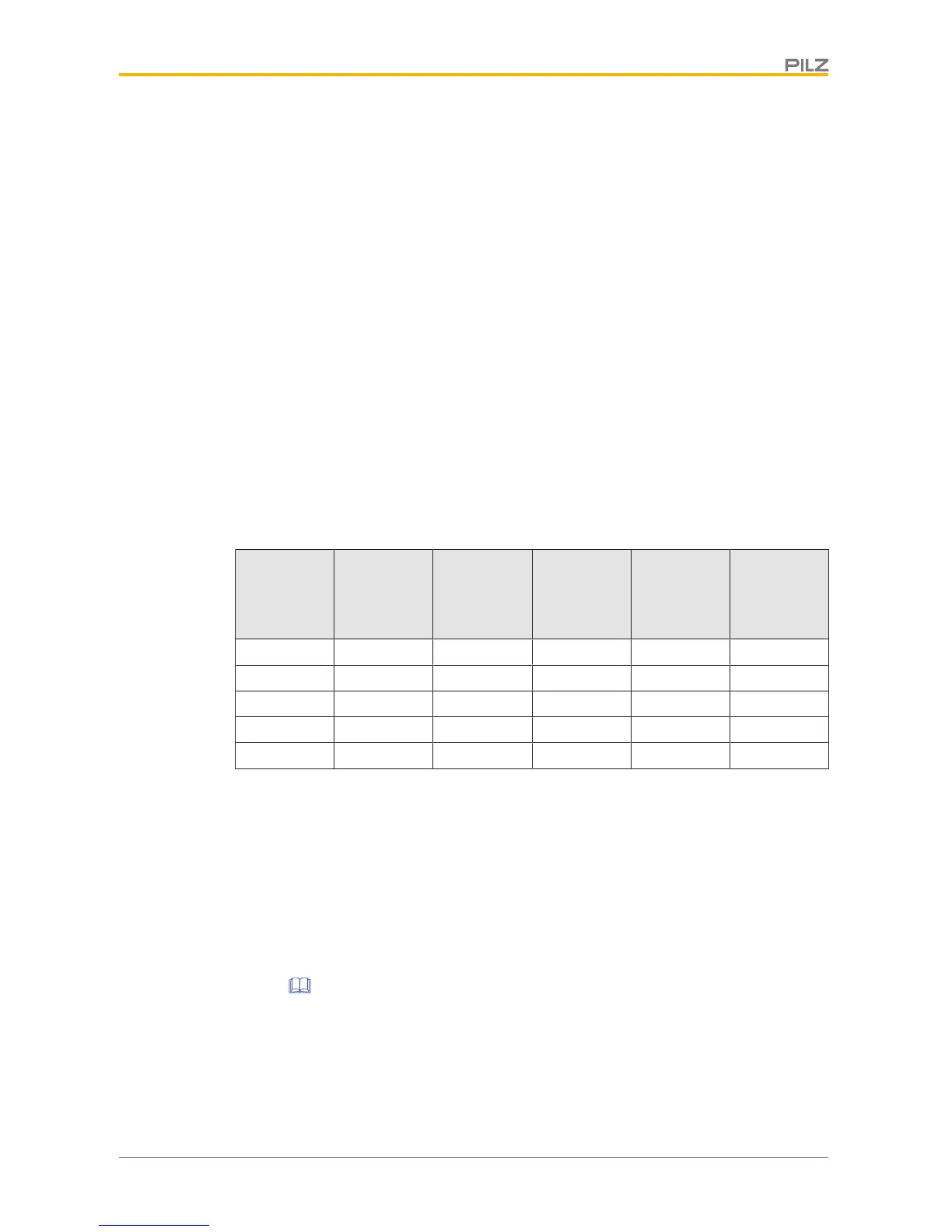
Electrical states of the inputs and outputs (when switch is ready for operation:
Power / Fault LED is green):
Actuator in
the re-
sponse
range
Safety input
S11
Safety input
S21
Safety out-
put 12
Safety out-
put 22
Signal out-
put Y32
(without use
of the SDD)
Yes High High High High High
Yes Low Low Low Low High
No x x Low Low Low
Yes High Low High Low High
Yes Low High Low High High
x: High or low signal
Feasibility monitoring for safety inputs S11 and S21
} If one safety input switches from high to low, while the other safety input remains high,
an unequal status is displayed: Input LED flashes yellow
} If this safety input switches back from low to high, while the other safety input remains
high, a feasibility error is displayed and a partial operation lock is triggered: Input LED
flashes yellow
A switch to a high signal will only lead to normal switch operation if both inputs had a low
signal. From this moment on, the switch to high may occur (partial operation lock see Error
display [ 22]).
} Diagnostic input Y1
If a fieldbus module of the SDD is used, the diagnostic input Y1 is automatically activ-
ated and data is read.
If no fieldbus module of the SDD is used, the diagnostic input Y1 is not used.

 Loading...


