PSEN cs1.1p
Operating Manual PSEN cs1.1p
21095-EN-10
13
} The inputs and outputs of the safety switch must have a protective separation to
voltages over 60 VDC.
INFORMATION
Only use safety relays with a 24 VDC supply voltage. Safety relays with a
wide-range power supply or in AC device versions have internal potential
isolation and are not suitable as evaluation devices.
} The supply voltage to the safety switch must be protected with a 2 A to 4A quick-acting
fuse.
} Ensure the wiring and EMC requirements of IEC 60204-1 are met.
} When connecting in series, consider the requirements of manipulation protection and
the protection against bypassing or from overriding the safety switch (ENISO14119).
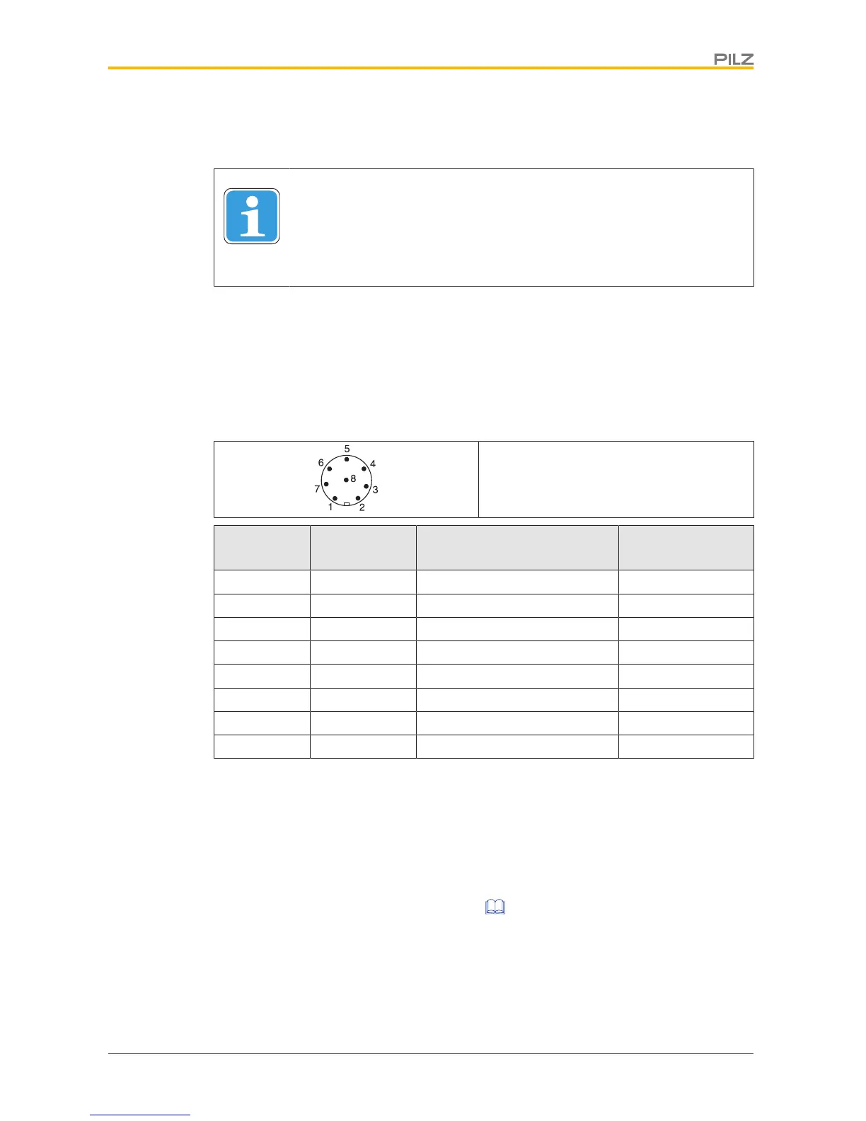
Terminal assignment connectors
8-pin M12 connector
PIN
Connection
designation Function Wire colour
1 S21 Input, channel 2 white
2 A1 +24 VUB brown
3 12 Output, channel1 green
4 22 Output, channel2 yellow
5 Y32 Signal output/diagnostic output grey
6 S11 Input, channel 1 pink
7 A2 0 V UB blue
8 Y1 Diagnostics input red
The wire colour also applies for the cable available from Pilz as an accessory.
Connection to evaluation devices
Make sure that the selected evaluation device has the following property:
} OSSD signals are evaluated through 2 channels with feasibility monitoring
Please note:
} Information given in the Technical details [ 23] must be followed.
} The use of Safety Device Diagnostics is described in the System Description "Safety
Device Diagnostics".

 Loading...


