PSEN cs1.1p
Operating Manual PSEN cs1.1p
21095-EN-10
12
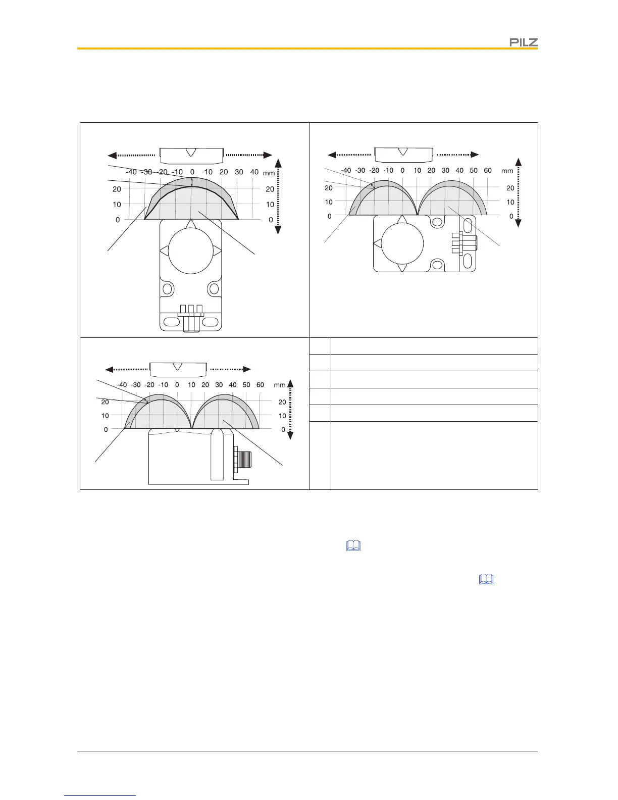
Lateral and vertical offset
Direction of actuation, front
[1] Hysteresis
[2] Typical operating distance S
O
[3] Typical release distance S
r
[4] Offset in mm
[5] Operating distance in mm
[6] Response range
Wiring
Please note:
} Information given in the Technical details [ 23] must be followed.
} The max. cable length l
max
in the input circuit is calculated from
– the max. cable capacitance at the safety outputs (see Technical data [ 23]).
– the minimum permitted supply voltage at the sensor (19.2 V).
} When the safety inputs of the safety switch are controlled by an upstream device, and
they are not wired with 24V,
– They must be monitored for shorts across the contacts in dependence of the Per-
formance Level or SIL level to be achieved or
– The faults at the safety inputs that can occur by shorts across contact will have to
be excluded by suitable measures (e.g. wiring in accordance with EN 60204-1).
} The power supply must meet the regulations for extra low voltages with protective sep-
aration (SELV, PELV).

 Loading...


