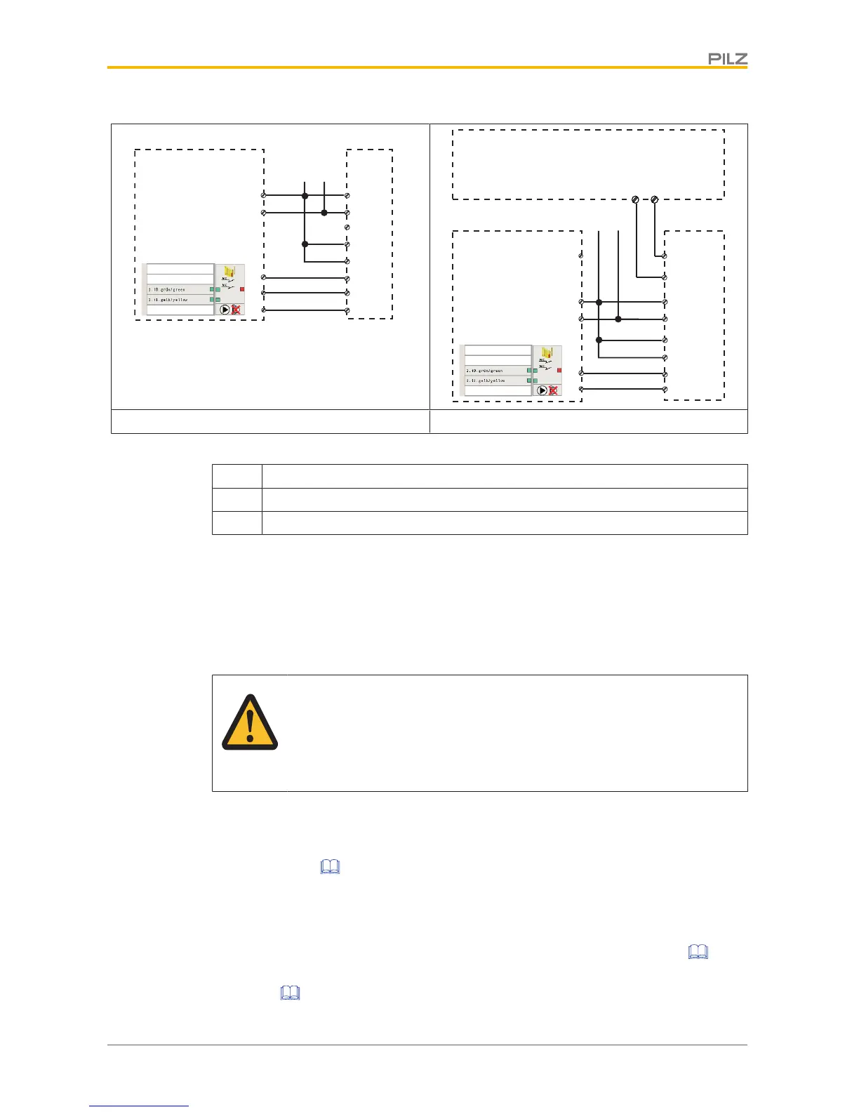
Without SDD With SDD
Legend:
I0 Input OSSD
I1 Input OSSD
I2 Signal input
Teaching in the actuator
Any Pilz actuator PSEN cs1.1) is detected as soon as it is brought into the response range.
Installation
CAUTION!
The unit's properties may be affected if installed in an environment contain-
ing electrically or magnetically conductive material. Please check the oper-
ating distances and the assured release distance.
} The safety switch and actuator should be installed opposite each other in parallel.
– Make sure that the actuator is aligned to the marking on the sensor that guarantees
the operating distance required by the plant design (see Operating
distances [ 11]).
} Safety switches and actuators should be permanently secured using M5 safety screws
with a flat head (e.g. M5 cheese-head or pan head screws).
} Protect the actuator from contamination.
} Torque setting: Please note the information provided under Technical details [ 23].
} The distance between two safety switches must be maintained (see Technical
details [ 23]).

 Loading...


