PSEN cs1.1p
Operating Manual PSEN cs1.1p
21095-EN-10
21
} Make sure that the safety switch and actuator cannot be used as an end stop.
} Please note the installation measures in accordance with EN ISO 14119 for a safety
switch design 4 and with level of coding Low
} For simpler installation, the mounting brackets (see Order reference for
Accessories [ 27]) can be used.
} If using angled connector plugs, note the defined angle of the cable routing.
CAUTION!
Possible loss of the safety function by changing the release distance S
ar
with non-flush installation
Installing the safety switch non-flush within electrically or magnetically con-
ductive material, the value for the assured release distance S
ar
can change.
– Check the assured release distance S
ar.
Procedure:
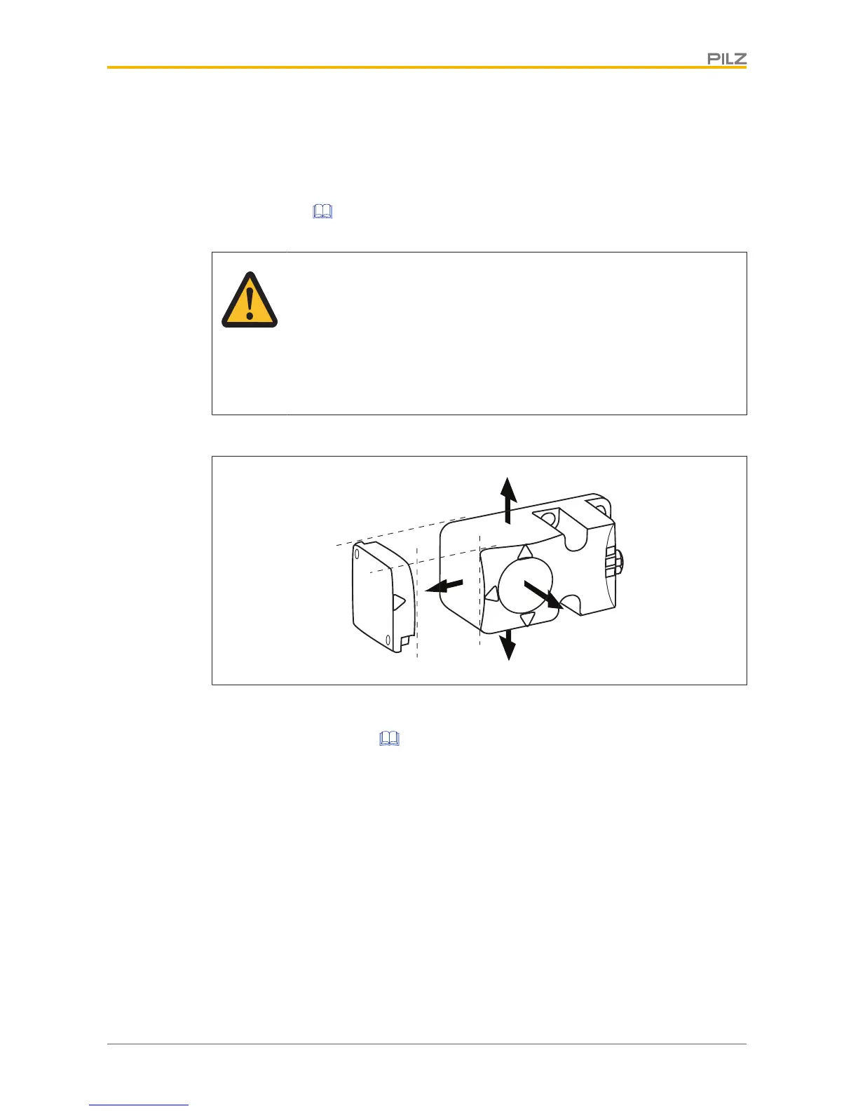
Fig.: Sensing faces on the sensor
1. Drill holes (for M5 screws) in the mounting surface to secure the actuator and sensor
(see Dimensions in mm [ 23]).
2. Use a screw to fix the sensor to the mounting surface.
Make sure that the sensor marking that is be used for operation can be operated using
the actuator from the right side.
3. Do not fully tighten the second screw on the safety switch.
4. Use a screw to fix the actuator to the mounting surface.
Make sure that the actuator with the printed side points towards the marking on the
sensor.
5. Do not fully tighten the second screw on the actuator.
6. Align the safety switch and tighten the screws.
7. Align the actuator and tighten the screws.

 Loading...


