PSEN sl-0.5p 1.1
Operating Manual PSEN sl-0.5p 1.1
21904-EN-10
9
} LEDs for
– Supply voltage/fault
– Gate closed
– State of the inputs
– State of the magnetic guard locking device
} M12, 8-pin male connector
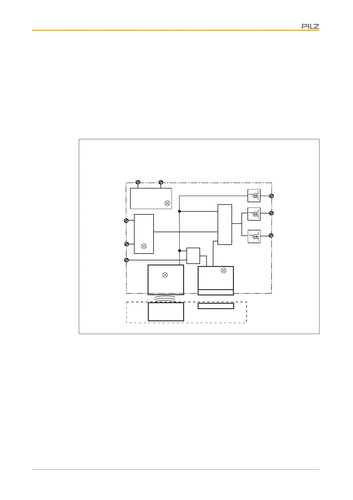
Function description
U
B
A1 A2
S31
12
22
Power supply
Power/Fault
&
&
Safety Gate
Lock
Receiver
Magnet
Actuator
Input
S21
S11
&
Y32
There is a high signal at safety outputs 12 and 22 if the following occur simultaneously:
} The actuator is within the response range (safety gate closed) and
} There is a high signal at the inputs S11 and S21 and
} There is a high signal at the input S31 (control command for magnetic guard locking)
and
} The holding force of the locking magnet has been tested successfully.
There is a low signal at safety outputs 12 and 22 if at least one of the following conditions
are met:
} The actuator is outside the response range or
} There is a low signal at the inputs S11 or S21 or
} There is a low signal at the input S31 (control command for magnetic guard locking) or
} The holding force of the locking magnet has not been tested successfully.

 Loading...