PSEN sl-1.0p 1.1/1.1 VA
Operating Manual PSEN sl-1.0p 1.1/1.1 VA
1003821-EN-12
12
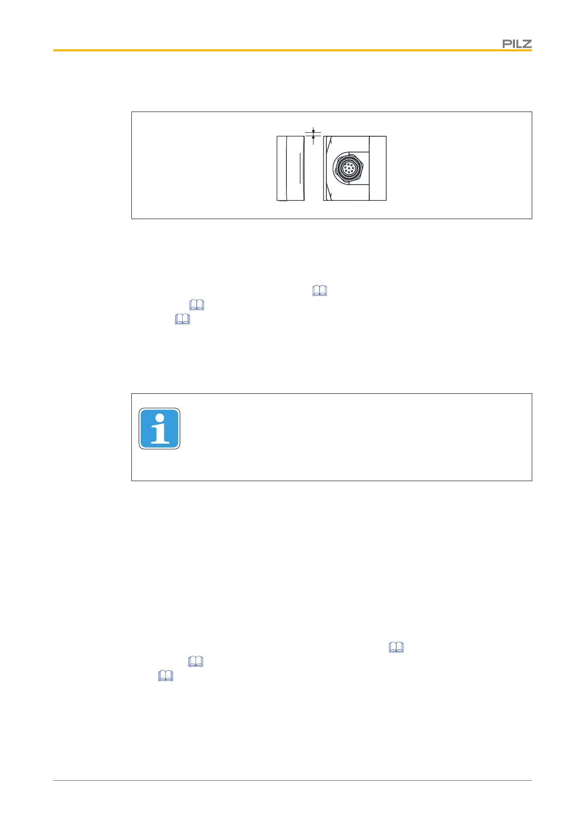
} Max. lateral offset: 3 mm
Wiring
Please note:
} You must comply with the specifications stated in the technical details (see Technical
details: System with normal acutator [ 27], System with free-moving
actuator [ 30], System with normal actuator and stainless steel base
plate [ 34]).
} The power supply must meet the regulations for extra low voltages with protective sep-
aration (SELV, PELV).
} The inputs and outputs of the safety switch must have a protective separation to
voltages over 60 VDC.
INFORMATION
Only use safety relays with a 24 VDC supply voltage. Safety relays with a
wide-range power supply or in AC device versions have internal potential
isolation and are not suitable as evaluation devices.
} Ensure the wiring and EMC requirements of EN 60204-1 are met.
} When connecting in series, make sure you comply with the wiring technology require-
ments (DIN EN 60204-1) and manipulation protection requirements (EN ISO 14119).
Guidelines for cable length
The max. cable length depends on the voltage drop at the safety switches. The level of
voltage drop is determined by the:
} Cable resistance
} Current of the device and the current load of the outputs
If the level of the supply voltage at the device connector falls below the minimum permitted
value (see Technical details:
System with normal actuator [ 27], System with free-mov-
ing actuator [ 30], System with normal actuator and stainless steel base
plate [ 34]), the electromagnet is no longer activated reliably. The "Lock" LED registers
an error when guard locking.

 Loading...

