Safe monitoring relays
Up to PL e of EN ISO 13849-1
PSWZ X1P
NSG-D-2-336-2009-11Pilz GmbH & Co. KG, Felix-Wankel-Straße 2, 73760 Ostfildern, Germany
Telephone: +49 711 3409-0, Telefax: +49 711 3409-133, E-Mail: pilz.gmbh@pilz.de
-2
Function description
][Funktionen_einkanalig_Stillstand
The device uses two separate measur-
ing channels to measure the regener-
ated voltage, induced from the motor
during the rundown period or during
start-up. If the voltage falls below the
set response value (standstill thresh-
old), the standstill monitor enables the
monitored plant. If the voltage ex-
ceeds the set release value, the stand-
still monitor disables the monitored
plant.
To reactivate, the voltage at both
channels must fall below the response
value U
on
within the time t
g
(simultane-
ity monitoring). To do this the feed-
back loop Y1-Y2 must be closed. If the
simultaneity requirement is exceeded,
the standstill monitor does not enable
the monitored plant. The unit can be
reactivated by switching 24 VDC on
and off at the RESET input.
The response value U
on
can be set
jointly for both channels in order to suit
the motor that is to be monitored. The
release value U
off
(hysteresis) corre-
sponds to twice the response value.
When used with frequency converters,
the PSWZ X1P cannot detect standstill
until the controller inhibit has been
switched off.
After the supply voltage is switched
on, the unit performs a self test. The
unit simulates a situation in which the
release value is exceeded and the
measuring circuit has an open circuit.
The correct function of the output relay
and feedback loop is also tested. The
test takes ca. 1.5 s.
][Funktionen_zweikanalig_S tillstand
Operating modes:
` Single-channel operation:
– One measuring circuit affects
both channels
– No redundancy (failsafe) in the
measuring circuits
` Dual-channel operation:
– Two redundant (identical) meas-
uring circuits affect channel 1
and 2
– Monitoring of voltages in the
measuring circuit (failsafe in the
event of a short circuit)
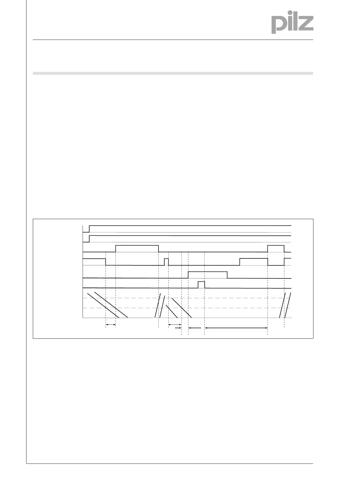
Timing diagram
Zeitdiagramm
Key
` POWER: Supply voltage
` UL1/UL2: Input circuitL1, L2, L3
` Feedback: Feedback loop Y1-Y2
` Output safe: Safety contacts 13-14,
23-24
` Output aux: Auxiliary contact 41-42
` Semi Y35: Semiconductor output
for fault signal
` RESET: Reset input RESET
` U
on
: Response value
` U
off
: Release value
` t
g
: Simultaneity
Wiring
][Verdrahtung_Si_unverz_1Hi_unverz_Stillstand
Please note:
` Information given in the “Technical
details” must be followed.
` Outputs 13-14, 23-24 are safety
contacts, output 41-42 is an auxilia-
ry contact (e.g. for display).
` To prevent contact welding, a fuse
should be connected before the
output contacts (see technical de-
tails).
` Use copper wire that can withstand
60/75 °C.
` When used with converters: Use
screened cable for the wiring be-
tween the standstill monitor and the
motor. Connect the cable screening
on the motor.
POWER
Semi Y35
Output safe
Feedback
t < tg
1,5 s
t > tg
RESET
UL1/UL2
U
on
U
off
50 ms
Output aux

 Loading...