Specications
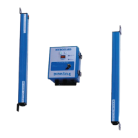
Metal Box Controller Module
1
Input Power
18 to 33 VDC @ 10 W (optional)
90 to 140 VAC @ 12 W (standard)
128 to 240 VAC @ 12 W (optional)
All AC voltages work with 50 or 60 Hz
Fuses
AC power: 1 AMP Slow Blow (250VAC)
DC power: 1 AMP Fast Blow
Output Circuits (all isolated)
Terminals #12-13: N.O. (held closed when Green)
control reliable dry STOP circuit, wired through K1 &
K2 relays. 4A @ 120vac recommended max
Terminals #14-15: N.O. (held closed when Green)
control reliable dry STOP circuit, wired through K1 & K2
relays. 4A @ 120vac recommended max
Terminals #9-10-11: N.O. (held closed when
Green) – common – N.C. (held open when Green)
dry auxiliary circuit, wired through K3 relay.
4A @ 120vac recommended max
Alarm + - : N.O. (held closed when powered and NO
FAULTS) dry auxiliary circuit, wired through K4 relay.
4A @ 120vac recommended max
For Older Control boxes prior to
October 2007: Both terminals #12-13 and #14-15 must
be used to achieve a control reliable STOP circuit. Newer
control boxes can use either or both sets of terminals.
Indicators
External:
OK/CLEAR Green
BLOCK/FAULT Red
AUTO/FLOAT ACTIVE Yellow
SLAVE DISAGREEMENT Red
The Diagnostics Display is a four-digit
alphanumeric with scroll
Internal:
+12V (RED) D2 CINN INT. (GRN) D10
+5V (YEL) D4 EXT RELAY (GRN) D11
+5V (YEL) D3 -5V (GRN) D17
FAULT RELAY (GRN) D21
Construction:
Control Unit: All 18 Gauge painted steel
NEMA 12 lockable box with sealed front
panel and sealed cable entry ttings (8 lbs.).
Pylons: Heavy-duty aluminum extrusion
NEMA 4. Replaceable IR lens.
Sealed bulkhead positive locking circular
connectors. (Optional polycarbonate
protective tube guards).
Cables: Emitter 20’/ Receiver 8’ (supplied
standard). Shielded PVC 22 AWG cable
(optional cable lengths available).
Temperature Range 32° to 120° F
Dimensions
Controller Module: (see Dimensions)
Pylons: 1.45” (36.83mm) square (see
Dimensions)
Beam Spacing
.5” (12.7mm) standard
1” (25.4mm) (optional). The Floating Blank
option changes the effective beam spacing.
Minimum Object Sensitivity:
.5” (12.7mm) beam spacing is .55” (14mm)
1” (25.4mm) beam spacing is 1.18” (30mm)
Response Time < 30 mSec total
Scanning Frequency 5.9 KHz
Shock Tested to withstand high vibration applications.
Self-Checking every 20 milliseconds
Scanning Distance All units are supplied standard
with a 20’ (6.1m) scanning capability. Extended
range units are available and must be specied -- 50’
maximum (15.2m).
Maximum Operating Distance Stated as last two
digits in model number.