Controller Module Setup
1 Mute-Out Input LS4 (optional)
2 Remote Latch reset input
3 Mute-Out LS5 (optional)
4 Ground for Terminals
5 Cincinnati Interface + Input
6 Cincinnati Interface – Input
7 External relay monitor input
8 External relay monitor input
9 Aux relay K3 (N.O.) close when Green
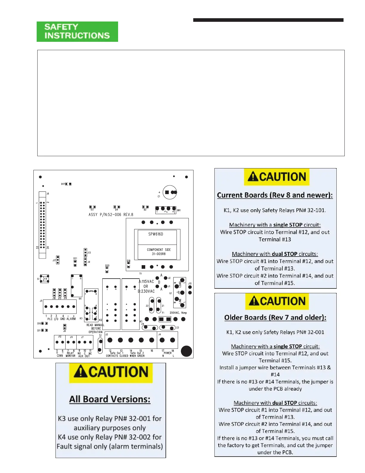
Table 3: Controller Module Connection Chart (Lower Board)
10 Aux relay K3 (common)
11 Aux relay K3 (N.C.) close when Red
12-13 Safety Output #1 N.O. close when Green
14-15 Safety Output #2 N.O. close when Green
16 Case Ground (Earth)
17-18 Neutral (-) and Line (+)
alarm Dry relay opens on fault or loss of power
Figure 5: Controller Module (Lower Board)
Installation Procedures
Metal Box Controller Module
13