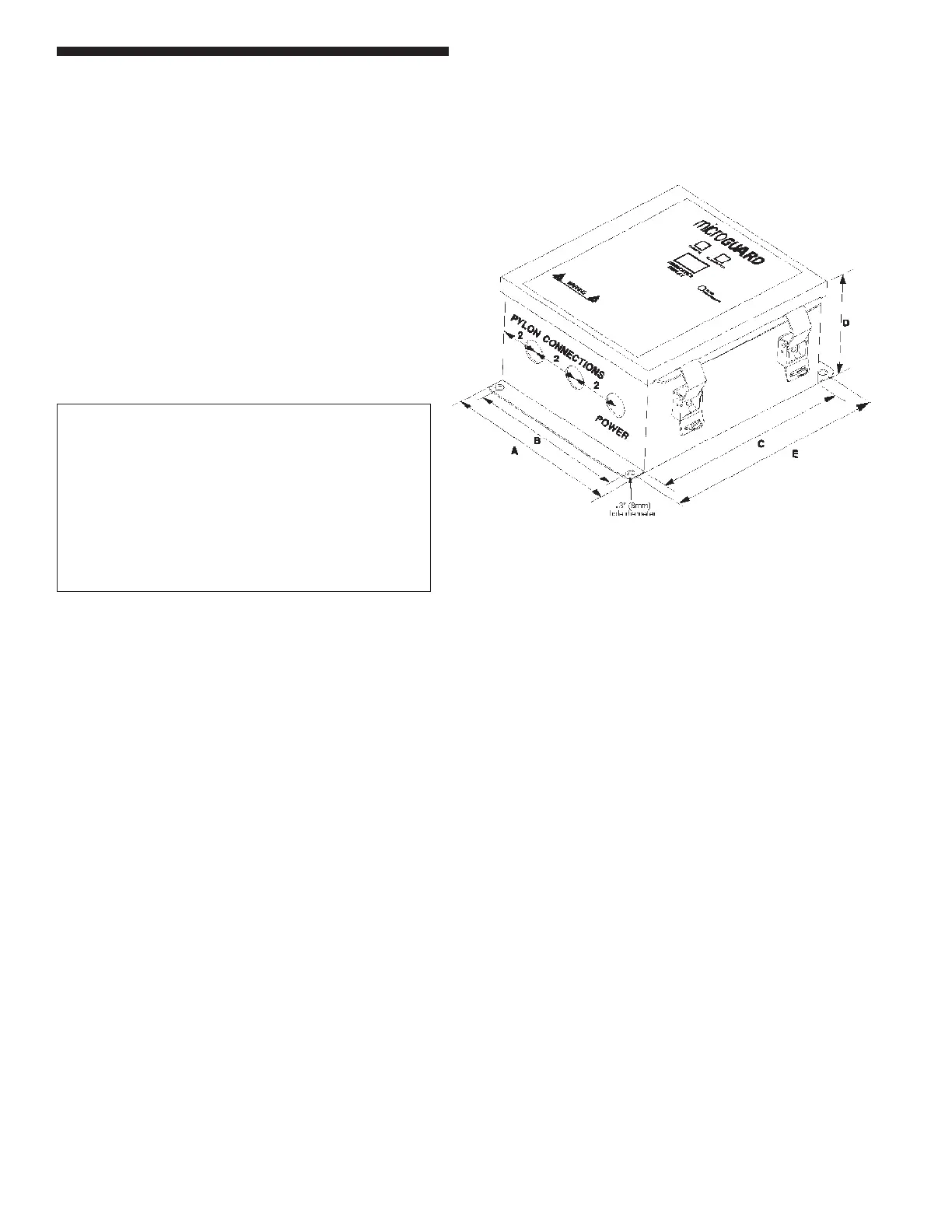
Controller Module
The Emitter cable plugs into a bulkhead connector on
the bottom right of the controller. The Receiver cable
plugs into a bulkhead connector on the bottom middle of
the controller. All other signals, including power, enter
through the knockout provided on the bottom left of the
controller. The bulkhead connectors are water/dust/oil
tight. Cables lock onto the bulkhead connectors with
a ¼ turn.
Tol. +/- 0.10” / 2.54mm
Figure 11: Controller Module Dimensions
Table 6: Controller Module Dimensions
Dim Single Multiple
(in/mm) (in/mm)
A 7” / 177.8 8” / 203.2
B 4” / 101.6 7” / 177.8
C 8” / 203.2 9” / 228.6
D 4” / 101.6 4” / 101.6
E 8.65” / 215.9 9.85” / 248.9
Dimensions
Metal Box Controller Module
20