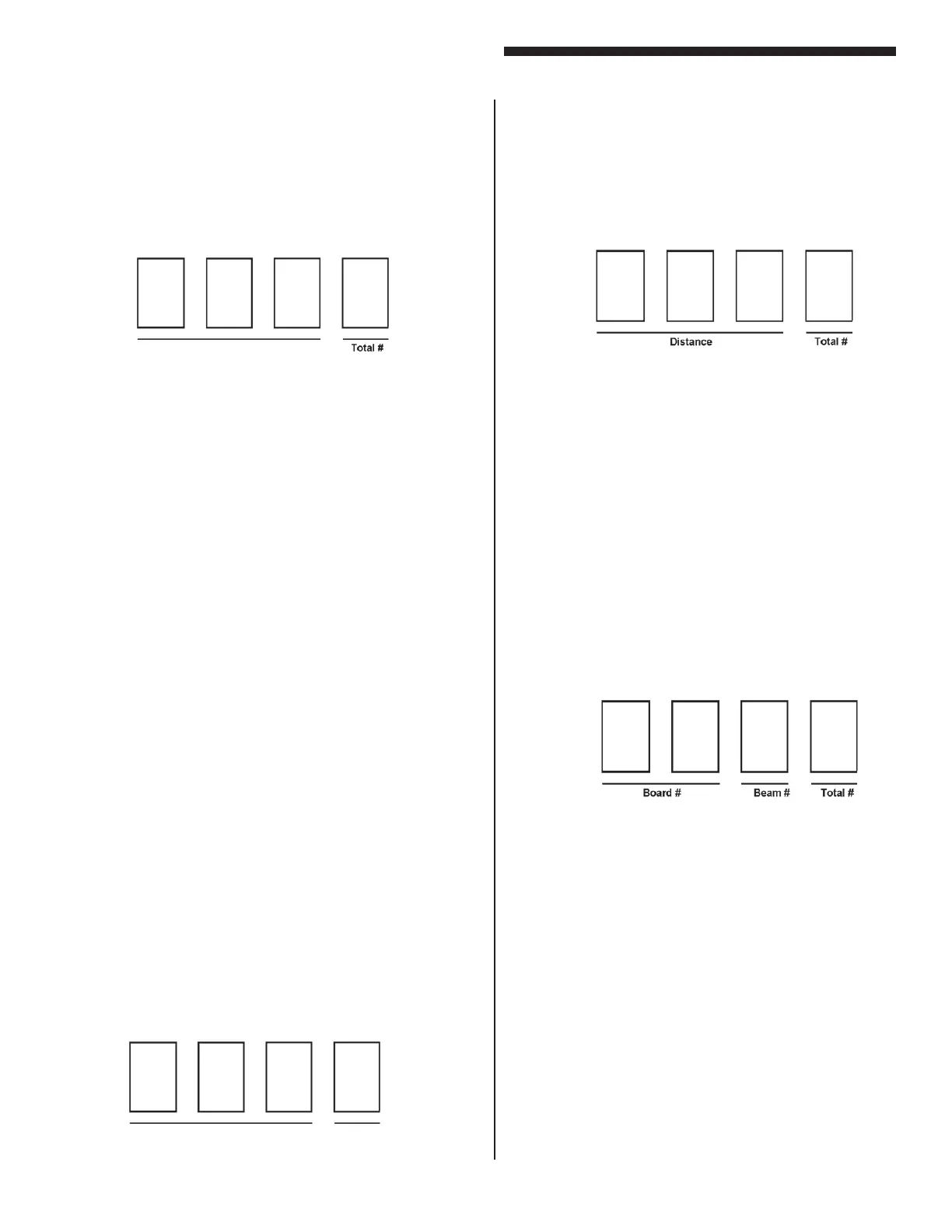
Obstruction or Misalignment
When the curtain is obstructed or misaligned, the display
will present four numbers to indicate location of obstruction
or misalignment. Not a scrolling message.
Distance
The rst three numbers displayed represent (in inches) the
rst obstructed or misaligned beam on the guard starting
from the cable end of the pylon. The third digit is blank for
whole inches and “5” for half inches.
Total #
The last digit indicates the total number of beams blocked or
misaligned. The digit counts in Hexadecimal (0 to F = 0 to 15
beams). A “>” sign indicates more than 15 beams missing.
“A”=10 beams, “B”=11 beams, “C”=12 beams, “D”=13
beams, “E”=14 beams, “F”=15 beams
Error Conditions
When a scrolling ERROR message is displayed, the end of
the message will display a set of numbers to indicate where
along the pylon the problem resides.
The rst two numbers displayed represent the rst problem
beam on the guard starting from the cable end of the pylon.
The third number represents the total number of beams
blocked on the guard. Boards inside each pylon are exactly
four inches long. Using this you can determine which board
in the pylon is bad.
Denitions
BOARD #: Indicates rst board on which a problem was
detected (01 to 17).
(i.e., 01 = board nearest cable connection)
BEAM #: Indicates first problem beam on the board
indicated above (1 to 8).
(i.e., 1 = rst beam on board, 8 = last beam on
board)
TOTAL #: Indicates total number of blocked beams on the
curtain.
(i.e., 1 to 9 beams then A to F = 10 to 15 beams)
Appendix “A”
Diagnostics and Troubleshooting
A-1
NOTE: For all guards with socket
microprocessors (prior to 6/2012)
Obstruction or Misalignment
When the curtain is obstructed or misaligned, the display will
present four numbers to indicate location of obstruction or
misalignment. Not a scrolling message.
Beam # (Distance)
The rst three numbers displayed represent the beam # of the
rst obstructed or misaligned beam. Beam #1 is located at the
cable end of the pylon and counts up. If you have a ½” beam
spacing (-0F), the number increment every ½”. If you have 1”
beam spacing (-0F1), the number increments every 1”. If you
have 4” beam spacing (-0F4), the number increments by 1” for
the rst 4 beams, then jumps a 4” gap, then increments by 1” for
the next 4 beams, then another gap, etc., etc.
Note: If you have multiple pylons to one control box (-SC), the
cable end of the 2nd pylon is the next beam# after the 1st pylon,
etc. etc.
Note: If you tap the Reset button (inside of the door), the Display
will increment to show you the next blocked beam
Note: You can also use the USB port to read the obstruction
locations (see appendix D)
Total #
The last digit indicates the total number of beams blocked or
misaligned. The digit counts in Hexadecimal (0 to F = 0 to 15
beams). A “>” sign indicates more than 15 beams missing.
“A”=10 beams, “B”=11 beams, “C”=12 beams, “D”=13 beams,
“E”=14 beams, “F”=15 beams
Examples:
604 = The 60th beam is blocked along with 3 more beams
10A= The 10th beam is blocked along with 9 more beams
Error Conditions
When a scrolling ERROR message is displayed, the end of the
message will display a set of numbers to indicate where along
the pylon the problem resides.
Beam # (Distance)
As dened above under “Obstruction or Misalignment.”
NOTE: For all guards with a USB connector
on the inside of the door (after 6/2012)
A - 1
Appendix “A”
Diagnostics & Troubleshooting
Er Er
Er Er
Er
rr
rr
r
or Conditionsor Conditions
or Conditionsor Conditions
or Conditions
When an ERROR message is displayed, the end of the
message will display a set of numbers to indicate where
along the pylon the problem resides.
The first two numbers displayed represent the first
problem beam on the guard starting from the cable end
of the pylon. The third number represents the total
number of beams blocked on the guard. Boards inside
each pylon are exactly four inches long. Using this you
can determine which board in the pylon is bad.
D
efinitions
BOARD #: Indicates first board on which a problem was
detected (01 to 17).
(i.e., 01 = board nearest cable connection)
BEAM #: Indicates first problem beam on the board
indicated above (1 to 8).
(i.e., 1 = first beam on board, 8 = last beam
on board)
TOTAL #: Indicates total number of blocked beams
on the curtain.
(i.e., 1 to 9 beams then A to F = 10 to 15
beams)
ObstrObstr
ObstrObstr
Obstr
uction or Misalignmentuction or Misalignment
uction or Misalignmentuction or Misalignment
uction or Misalignment
When the curtain is obstructed or misaligned, the display
will present four numbers to indicate location of
obstruction or misalignment.
Distance
The first three numbers displayed represent (in inches)
the first obstructed or misaligned beam on the guard
starting from the cable end of the pylon. The third digit
is blank for whole inches and “5” for half inches.
To
tal #
The last digit indicates the total number of beams blocked
or misaligned. The digit counts in Hexadecimal (0 to F
= 0 to 15 beams). A “>” sign indicates more than 15
beams missing.
“A”=10 beams, “B”=11 beams, “C”=12 beams, “D”=13
beams, “E”=14 beams, “F”=15 beams
C
omputing Object Size
To compute an object’s size, use the following formula:
size(inches) = TOTAL# x 0.5"
This can be used to evaluate an object’s size up to 7.5"
in diameter.
(i.e., TOTAL# = 3 so SIZE = 1.5")
(i.e., TOTAL# = D so SIZE = 6.5")
Exa
mples
1255 = First obstruction located 12.5" from
connector, size of object is 2.5"
05 A = First obstruction located 5.0" from
connector, size of object is 5.0"
A - 1
Appendix “A”
Diagnostics & Troubleshooting
Er Er
Er Er
Er
rr
rr
r
or Conditionsor Conditions
or Conditionsor Conditions
or Conditions
When an ERROR message is displayed, the end of the
message will display a set of numbers to indicate where
along the pylon the problem resides.
The first two numbers displayed represent the first
problem beam on the guard starting from the cable end
of the pylon. The third number represents the total
number of beams blocked on the guard. Boards inside
each pylon are exactly four inches long. Using this you
can determine which board in the pylon is bad.
D
efinitions
BOARD #: Indicates first board on which a problem was
detected (01 to 17).
(i.e., 01 = board nearest cable connection)
BEAM #: Indicates first problem beam on the board
indicated above (1 to 8).
(i.e., 1 = first beam on board, 8 = last beam
on board)
TOTAL #: Indicates total number of blocked beams
on the curtain.
(i.e., 1 to 9 beams then A to F = 10 to 15
beams)
ObstrObstr
ObstrObstr
Obstr
uction or Misalignmentuction or Misalignment
uction or Misalignmentuction or Misalignment
uction or Misalignment
When the curtain is obstructed or misaligned, the display
will present four numbers to indicate location of
obstruction or misalignment.
D
istance
The first three numbers displayed represent (in inches)
the first obstructed or misaligned beam on the guard
starting from the cable end of the pylon. The third digit
is blank for whole inches and “5” for half inches.
To
tal #
The last digit indicates the total number of beams blocked
or misaligned. The digit counts in Hexadecimal (0 to F
= 0 to 15 beams). A “>” sign indicates more than 15
beams missing.
“A”=10 beams, “B”=11 beams, “C”=12 beams, “D”=13
beams, “E”=14 beams, “F”=15 beams
C
omputing Object Size
To compute an object’s size, use the following formula:
size(inches) = TOTAL# x 0.5"
This can be used to evaluate an object’s size up to 7.5"
in diameter.
(i.e., TOTAL# = 3 so SIZE = 1.5")
(i.e., TOTAL# = D so SIZE = 6.5")
Exa
mples
1255 = First obstruction located 12.5" from
connector, size of object is 2.5"
05 A = First obstruction located 5.0" from
connector, size of object is 5.0"
A - 1
Appendix “A”
Diagnostics & Troubleshooting
Er Er
Er Er
Er
rr
rr
r
or Conditionsor Conditions
or Conditionsor Conditions
or Conditions
When an ERROR message is displayed, the end of the
message will display a set of numbers to indicate where
along the pylon the problem resides.
The first two numbers displayed represent the first
problem beam on the guard starting from the cable end
of the pylon. The third number represents the total
number of beams blocked on the guard. Boards inside
each pylon are exactly four inches long. Using this you
can determine which board in the pylon is bad.
D
efinitions
BOARD #: Indicates first board on which a problem was
detected (01 to 17).
(i.e., 01 = board nearest cable connection)
BEAM #: Indicates first problem beam on the board
indicated above (1 to 8).
(i.e., 1 = first beam on board, 8 = last beam
on board)
TOTAL #: Indicates total number of blocked beams
on the curtain.
(i.e., 1 to 9 beams then A to F = 10 to 15
beams)
ObstrObstr
ObstrObstr
Obstr
uction or Misalignmentuction or Misalignment
uction or Misalignmentuction or Misalignment
uction or Misalignment
When the curtain is obstructed or misaligned, the display
will present four numbers to indicate location of
obstruction or misalignment.
Distance
The first three numbers displayed represent (in inches)
the first obstructed or misaligned beam on the guard
starting from the cable end of the pylon. The third digit
is blank for whole inches and “5” for half inches.
To
tal #
The last digit indicates the total number of beams blocked
or misaligned. The digit counts in Hexadecimal (0 to F
= 0 to 15 beams). A “>” sign indicates more than 15
beams missing.
“A”=10 beams, “B”=11 beams, “C”=12 beams, “D”=13
beams, “E”=14 beams, “F”=15 beams
C
omputing Object Size
To compute an object’s size, use the following formula:
size(inches) = TOTAL# x 0.5"
This can be used to evaluate an object’s size up to 7.5"
in diameter.
(i.e., TOTAL# = 3 so SIZE = 1.5")
(i.e., TOTAL# = D so SIZE = 6.5")
Exa
mples
1255 = First obstruction located 12.5" from
connector, size of object is 2.5"
05 A = First obstruction located 5.0" from
connector, size of object is 5.0"
Beam #