( Connecting
the
units
)
Section
(-
)Ci!I
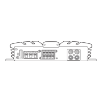
• Install and route the separately sold battery
wire
as
far
as
possible from the speaker wires.
Install and route the separately sold battery
wire, ground wire, speaker wires and the am-
plifier
as
far away
as
possible from the anten-
na,
antenna cable and tuner, 0
to 8 n
for
stereo
connection,
or
4 n to 8 n
for
monaural
and
other
bridge
connection.
Subwoofer
Nominal input:
Two·channeloutput Min,
135
W (GM-5400n
Min,
60W
(GM-3400n
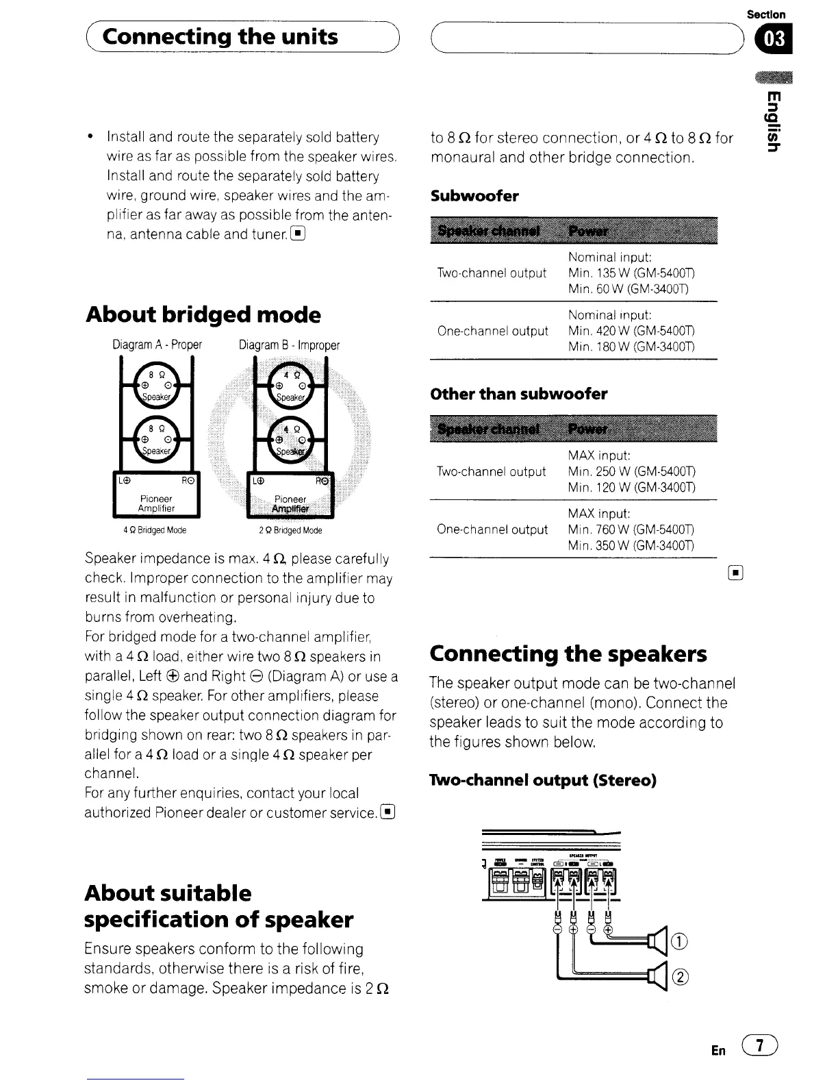
About
bridged
mode
Speaker impedance is max. 4
n.
please carefully
check. Improper connection to the amplifier may
result
in
malfunction or personal injury due to
burns from overheating.
For
bridged mode for a two-channel amplifier,
with a 4 n load, either wire two 8 n speakers
in
parallel, Left (f) and Right 8 (Diagram
A)
or use a
single 4 n speaker.
For
other amplifiers, please
follow the speaker output connection diag ram for
bridging shown
on
rear: two 8 n speakers
in
par-
allel for a 4 n load or a single 4 n speaker per
channel.
For
any further enquiries, contact your local
authorized Pioneer dealer or customer service. 0
Diagram
A-
Proper
Pioneer
Amplifier
4
Q
Bridged
Mode
Diagram
B-
Improper
2Q
Bridged
Mode
Nominal Input:
One-channel output Min,
420
W (GM-5400n
Min. 180W (GM-3400n
Other
than
subwoofer
MAX input:
Two-channel output Min.
250
W (GM-5400n
Min.
120
W (GM-3400n
MAX input:
One-channel output Min. 760W (GM-5400n
Min. 350W (GM-3400n
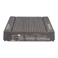
Connecting
the
speakers
The speaker
output
mode
can
be two-channel
(stereo)
or
one-channel
(mono),
Connect
the
speaker leads
to
suit
the
mode
according
to
the
figures
shown
below.
Two-channel
output
(Stereo)
About
suitable
specification
of
speaker
Ensure speakers
conform
to
the
following
standards,
otherwise
there
is a risk
of
fire,
smoke
or
damage. Speaker
impedance
is 2 n
En
CD
 Loading...