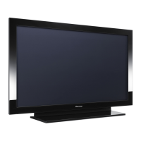
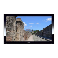
PX-42VM5J
29C00461
29C01431
24C05151
24C00091
29C01421
6S170004
6S170005
4
1
1
2
6
1
5
29C01471
29J01061
29J01072
29C01401
6S170003
6S170007
3
1
1
4
1
1
LD
PW
LD
TR
TS
TR
PD
PH
PN
PV
OM
AC
TM
TS
SW
RS
PA
PA
AU
AD
AU
PV FA
FB
TM
PM
CCD
AD
PN
RSSWPW
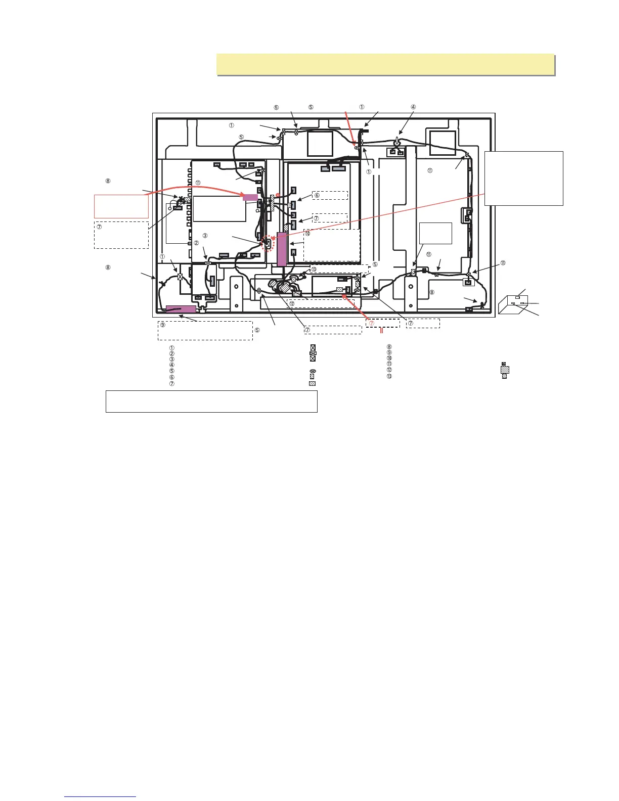
26.WIRING
(1)CLASS A
EDGING SADDLE(EDS-1208U) 29C00461 4
LUG(L60)
29C01471 3
EDGE SADDLE(TES-016NV)
29C01431 1
BARRIER(LD)
29J01061 1
EDGE SADDLE(TSB-1915) 24C05151
1
BARRIER(PA)
29J01072 1
LEAD CLAMPER(D5.2)
24C00091 2
CLAMP(MWC-2S)
29C01401 4
CLAMP(WS-2W-V0)
29C01421 6
CORE,FERRITE SFT-72SNB
6S170003 1
CORE,FERRITE TFT-081813N
6S170004 1
FERRITE CORE ESD-R-19 6S170007 1
FERRITE CORE ZCAT2032-930
6S170005 5
LD
PW
PM
LD
TR
TS
TR
PD
PH
PN
PV
PM
AC
Pass PD and PH.
Pass TM.
Pass TM.
Pass TM.
Pass PD and PH.
Bundle TM and TR.
Pass TM.
TM
TS
SW
RS
PA
PA
AU
Pass the AD and
fasten it with an
attached harness
band.
AD
Fix the AD with
Wound Lug
Pass LD.
Pass PW and RS.
Pass AD.
Pass AU and PV.
Pass TR.
Pass SW.
Using the barrier pinch the LD cable
so that it does not come in contact
with the radiator plate of the module.
Using the barrier
pinch the PA cable
so that it does not
come in contact with
the power supply side.
Pass PA.
Pass PN.
Pass AU.
Fix the SW with
Wound Lug
Pass PA.
x 2
Pass PA.
AC INLET
GREEN(GND)
BROWN
BLUE
Pass AU and SW.
Pass SW and TS.
Fix it with a filament
tape (19mm) making
sure that the connector
does not clog the hole.
Fix it with a
filament tape
(19mm).
Pass 2 turns AC and GND.
Pass 3 turns of GND.
Pass 3 turns of GND.
PW
PV
TM
FB
FA
PN
AD
AU
SW
RS
Label
side
CCD
It takes care that a core of AUDIO PKG does not run aground C3039.
and the connector to check for the freedom from floating.
CCD PWB
Refer to the second
page.
(Caution) There are two types
of lead-out ports.For the 42V
Series, the AD cable is brought
out of the lead-out port that is
apart from the AD (label side).
There is an engraved marking
of [V].
Fix the LD with
Wound Lug
26. WIRING
(Caution) ìTurnsî in the illustration below denotes the number of cable turns to be wound
around the ferrite core. (Example) 3 turns
3 turns of a cable wound around.
(Caution)"Turns"in the illustration below denotes the number of cable turns to be wound
around the ferrite core. (Example)3 turns
3 turns of a cable wound around.
(1) CLASS A
PDP-424MV-FI (CLASS A) Wiring Diagram
 Loading...