108
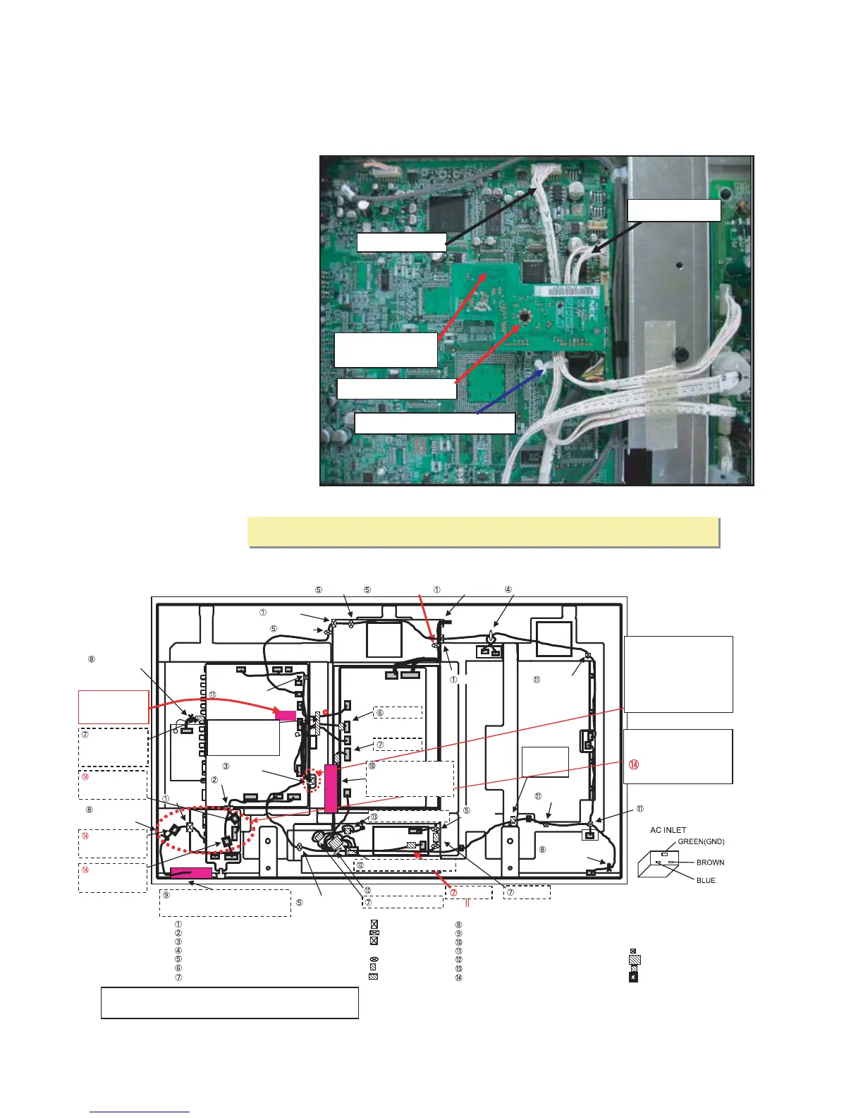
[Measures to be taken against connector go- through in the CCD PWB]
[Measures to be taken against connector go- through in the CCD PWB]
A problem of connector go- through in the CCD PWB can be caused by inadequate
workmanship such that a wiring material is pinched between the CCD PWB and the shield
lid. To eliminate this problem, wiring work should be carried out as specified below, so that
the PV and PM cables are never led to the CCD PWB.
[Model] For North America (Version A only)
[Wiring instructions] (Refer to the diagram
below.)
(1) Pass the PV and PM cables beneath
the CCD PWB.
(2) Fix the PV and PM cables by means of
lead clampers.
(3) Push the bush rivet and the connector
to check for the freedom from floating.
[Lead clampers to be used]
LEAD CLAMPER( D5.2): 24C00091
PDP- 424MV-FI (CLASS A) Wiring Diagram
PV CABLE
LEAD CLAMPER (D5.2)
BUSH RIVET
PM CABLE
CONNECTOR
(CCD PWB)
EDGING SADDLE(EDS-1208U) 29C00461 4
LUG(L60)
29C01471 3
EDGE SADDLE(TES-016NV)
29C01431 1
BARRIER(LD)
29J01061 1
EDGE SADDLE(TSB-1915) 24C05151
1
BARRIER(PA)
29J01072 1
LEAD CLAMPER(D5.2)
24C00091 2
CLAMP(MWC-2S)
29C01401 4
CLAMP(WS-2W-V0)
29C01421 6
CORE,FERRITE SFT-72SNB
6S170003 1
CORE,FERRITE TFT-081813N
6S170004 1
FERRITE CORE ESD-R-19 6S170007 1
FERRITE CORE ZCAT2032-930
6S170005 5
FERRITE CORE ZCAT1518-0730
6S170006
3
LD
PW
PM
LD
TR
TS
TR
PD
PH
PN
PV
PM
AC
Pass TM.
Pass TM.
Pass TM.
Pass TM.
TM
TS
SW
RS
PA
PA
AU
AD
Pass LD.
Pass PW and RS.
Pass AD.
Pass AU and PV.
Pass TR.
Pass SW.
Pass PA.
Pass PN.
Pass AU.
Pass PA.
x 2
Pass PA.
Pass AU and SW.
Pass SW and TS
PW
PV
TM
FB
FA
PN
AD
AU
SW
RS
Class B Model
Addition of cores (3 pcs.)
Addition of cores (3 pcs.)
FERRITE CORE
(ZCAT1518-730) 3 pcs.
CCD
Pass PD and PH.Pass PD and PH.
Bundle TM and TR.
Bundle AU, SW and PA.
(Caution) There are two types
of lead-out ports.
For the 42V Series, the AD
cable is brought out of the lead-
out port that is apart from the
AD (label side).
There is an engraved marking
of [V].
It takes care that a core of AUDIO PKG does not run aground C3039.
Fix it with a
filament tape
(19mm).
Using the barrier pinch
the PA cable so that it
does not come in contact
with the power supply side.
Fix the SW with
Wound Lug
Pass 3 turns of GND.
Pass 3 turns of GND.
Pass 2 turns AC and GND.
Fix it with a filament
tape (19mm) making
sure that the connector
does not clog the hole.
Label
side
Fix the AD with
Wound Lug
Fix the LD with
Wound Lug
CCD PWB
Refer to the second
page.
Pass the AD and
fasten it with an
attached harness
band.
Using the barrier pinch the LD cable
so that it does not come in contact
with the radiator plate of the module.
CCD board of PDP-424MV : Try to push the bush rivet
and the connector to check for the freedom from floating.
Pass LD.
(Compatible with
CLASS B)
Pass PW.
(Compatible with
CLASS B)
Pass RS.
(Compatible with
CLASS B)
(2) CLASS B
PDP-424MV (CLASS B) Wiring Diagram
PDP-42MVE1
(Caution) ìTurnsî in the illustration below denotes the number of cable turns to be wound
around the ferrite core. (Example) 3 turns
3 turns of a cable wound around.
(Caution)"Turns"in the illustration below denotes the number of cable turns to be wound
around the ferrite core. (Example)3 turns
3 turns of a cable wound around.
10-18
 Loading...