Do you have a question about the Pioneer PDP-R04G and is the answer not in the manual?
| HDMI Outputs | 1 |
|---|---|
| Component Video Outputs | 1 |
| Digital Audio Inputs (Optical) | 2 |
| Digital Audio Inputs (Coaxial) | 1 |
| Type | Receiver |
Compares PDP-R04G/TLDFR and PDP-R04E/WYVI6 models, highlighting differences.
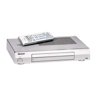
Details the components included in the product's packaging.
Lists all external parts and their corresponding part numbers.
Lists all parts related to the front panel assembly.
Provides overall block and schematic diagrams for signal routing.
Illustrates the signal flow throughout the receiver's main blocks.
Details the GR block of the MR Main Board Assembly.
Details the MICHAEL Main block of the MR Main Board Assembly.
Provides details for the MR Main Board Assembly, covering various blocks.
Details the AD Main block of the MR Main Board Assembly.
Details the AD Sub block of the MR Main Board Assembly.
Details the HDMI RX block of the MR Main Board Assembly.
Details the ROZ block of the MR Main Board Assembly.
Details the CELIA block of the MR Main Board Assembly.
Details the MIKE block of the MR Main Board Assembly.
Details the MIKE Flash block of the MR Main Board Assembly.
Details the MAIN UCOM block of the MR Main Board Assembly.
Details the MR I/F block of the MR Main Board Assembly.
Details the Regulator block of the MR Main Board Assembly.
Details the Tuner block of the AV Board Assembly.
Details the AV I/O block of the AV Board Assembly.
Details the SW block of the AV Board Assembly.
Details the AV_REG block of the AV Board Assembly.
Details the IF block of the AV Board Assembly.
Details the UCOM block of the AV Board Assembly.
Details the Teletext block of the AV Board Assembly.
Details the Memory_SW block of the AV Board Assembly.
Provides the schematic diagram for the MDR Assy.
Provides the schematic diagram for the SR Assy.
Details the front block of the Front Assy.
Details the sensor block of the Front Assy.
Provides the schematic diagram for the LED Assy.
Provides the schematic diagram for the REG Assy.
Details the schematic diagram of the Power Supply Unit.
Provides the schematic diagram for the AC SW Assy.
Displays expected waveform measurements on the MR Main Board.
Displays expected waveform measurements on the AV Board Assy.
Lists expected voltage values at various points on the MR Main Board.
Lists expected voltage values at various points on the AV Board Assy.
Lists expected voltage values for the MDR Assy.
Lists expected voltage values for the SR Assy.
Lists expected voltage values for the Front Assy.
Lists expected voltage values for the LED Assy.
Lists expected voltage values for the REG Assy.
Shows the PCB connection layout for AC SW and MDR assemblies.
Illustrates the PCB connection layout for the REG Assy.
Shows the PCB layout for the MR Main Board Assy, Side A.
Shows the PCB layout for the MR Main Board Assy, Side B.
Illustrates PCB connections for AV and SR Assys, Side A.
Shows the PCB connection layout for the SR Assy, Side B.
Displays the PCB layout for Front and LED Assys, Side A.
Lists main assemblies and their corresponding part numbers.
Details components and part numbers for the MR Main Board Assy.
Lists resistors and their part numbers for the MR Main Board Assy.
Lists semiconductors, coils, capacitors, and resistors for the HDMI RX Block.
Lists semiconductors, capacitors, resistors, and others for the AV SW Block.
Lists coils and filters with part numbers for the AV Board Assy.
Lists capacitors with part numbers for the AV Board Assy.
Lists resistors and their part numbers for the AV Board Assy.
Lists other components like connectors and sockets for the AV Board Assy.
Details semiconductors, coils, capacitors, resistors, and others for the Regulator Block.
Instructions on how to access the Service Factory mode.
Identifies scenarios requiring readjustment after replacing parts or assemblies.
Locates adjustment points on the AV Board Assy for calibration.
Step-by-step guide for performing AFC adjustment.
Step-by-step guide for performing RF-AGC adjustment.
Step-by-step guide for performing L'AFC adjustment.
Step-by-step guide for performing Video Level adjustment.
Explains the TRAP switch's purpose and important usage notes.
Describes how to connect and use SR connections for remote control.
Explains how to control the unit using RS-232C commands via a PC.
Details general operations and functions within Service Factory mode.
Lists remote control codes for Service Factory mode navigation and control.
Illustrates the structure and flow of the Service Factory menus.
Explains the main items displayed in the Service Factory mode.
Details settings for input functions within the Service Factory mode.
Covers SIG mode and screen size adjustments in Service Factory mode.
Details settings for color system and signal type in Service Factory mode.
Covers destination and other option settings in Service Factory mode.
Lists SIG modes, resolutions, and frequencies for video signals.
Lists SIG modes, resolutions, and frequencies for PC signals.
Lists and describes the operation items available in Information mode.
Shows firmware versions for common parts in Information mode.
Shows firmware versions for individual parts in Information mode.
Details types of power-down events and their on-screen display.
Lists panel shutdown types, on-screen display, and remarks.
Lists Media Receiver NG error codes and their descriptions.
Provides subcategory details for Media Receiver NG errors.
Notes on temperature sensor readings and reference values.
Details functions and content available in the Option mode.
Explains how to select frequencies while the mask is displayed.
Covers managing initial settings and destination settings in Initialize mode.
Details UART selection options and their corresponding RS-232C commands.
Provides a comprehensive list of RS-232C commands and their functions.
Details RS-232C commands related to input and output functions.
Lists RS-232C commands for mask and gain adjustments.
Lists RS-232C commands for subsystem adjustments.
Explains the RS-232C command to enable the TRAP switch.
Lists RS-232C commands for adjusting values.
Resets all data in the DIGITAL Assy to factory defaults.
Lists RS-232C commands for voltage adjustments.
Lists RS-232C commands for pulse outputs.
Lists commands to retrieve model and software version information.
Retrieves data related to the PDP pulse meter.
Retrieves the cumulative number of times the PDP was powered on.
Lists commands to clear various logs such as PD INFO and NG INFO.
Retrieves the power-down data log of the PDP.
Provides details and breakdown of NG data related to power-down events.
Retrieves the shutdown data log of the PDP.
Details the causes of shutdown for various data points.
Lists subcategories for 3-wire serial communication failures.
Lists subcategories for digital tuner failures.
Lists subcategories for IIC communication failures of the main microcomputer.
Provides general information for diagnosing issues with the unit.
Offers a systematic approach to troubleshooting common issues.
Guides users through diagnosing and fixing issues with the MONITOR OUT image.
Guides users through diagnosing and fixing issues with component or RGB signal display.
Guides users through diagnosing and fixing issues with headphone audio output.
Provides the first part of a guide to troubleshoot no sound from speakers.
Provides the second part of a guide to troubleshoot no sound from speakers.
Step-by-step guide to remove the metal bonnet top and bottom covers.
Step-by-step guide to remove the front panel section.
Guides on removing the front shield A and center stay.
Shows the location of the Power Supply Unit PCB within the chassis.
Shows the location of the MDR Assy PCB within the chassis.
Shows the location of the MR Main Board Assy PCB within the chassis.
Shows the location of the SR Assy PCB within the chassis.
Shows the location of the Front Assy PCB within the chassis.
Shows the location of the LED Assy PCB within the chassis.
Shows the location of the REG Assy PCB within the chassis.
Explains the processing related to the TRAP SW abnormality.
Details processing for power supply and DC-DC converter abnormalities.
Details processing for fan and temperature sensor abnormalities.
Describes LED lighting patterns corresponding to unit status.
Identifies defective points based on OSD indications and LED flashing.
Identifies defective points based on panel LED status.
Identifies defective points based on Media Receiver LED status.
Lists integrated circuits with their part numbers and descriptions.
Lists key ICs used in the main boards and their functions.
Details the function of each pin for the AD9883AKST-110 IC.
Provides the block diagram for the SM5301BS IC.
Shows the pin arrangement for the SM5301BS IC.
Provides the block diagram for the BA7078AF IC.
Details the function of each pin for the BA7078AF IC.
Provides the block diagram for the Sil9993CTG100 IC.
Shows the pin arrangement for the Sil9993CTG100 IC.
Provides the block diagram for the HY57V641620CT-7 DRAM.
Details the 16Mbit Flash Memory specifications.
Provides the block diagram for the MBM29LV160TE-90PFTN Flash Memory.
Details the function of each pin for the MBM29LV160TE-90PFTN Flash Memory.
Provides the block diagram for the CXA2069Q IC.
Provides the block diagram for the MSP3417G IC.
Shows the pin arrangement for the MSP3417G IC.
Details the VIF/SIF-PLL and FM-PLL/AM Demodulator functions.
Provides the block diagram for the TDA9818TS IC.
Details the functions of the AXF1119 TV Tuner.
Shows the pin arrangement for the AXF1119 TV Tuner.
Details the DC-DC Converter Unit, including pin functions.
Details the DC-DC Converter Unit, including pin functions.
Details the teletext decoding functions of the SDA6000 IC.
Shows the pin arrangement for the SDA6000 IC.
Details the function of pins 1-50 for the SDA6000 IC.
Details the function of pins 51-100 for the SDA6000 IC.
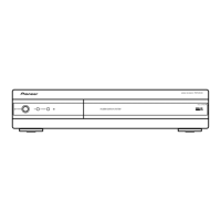
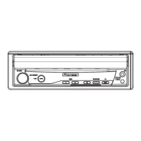
Identifies and describes the controls and indicators on the front panel.
Identifies and describes the terminals and connectors on the rear panel.
Explains the power button and input selection functions of the remote.
Describes how to select input sources using the remote.
Explains channel switching for TV/External and page selection for Teletext.
Covers two-digit mode selection and wide screen size adjustments.
Explains how to select the PC terminal as an input source.
Describes switching screen modes like 2-screen, PIP, and single-screen.
Explains channel selection and Teletext page navigation.
Covers sound multiplex mode and volume control functions.
Explains color selection and Electronic Programme Guide (EPG) functions.
Details Teletext features like hidden characters, return, and page updates.
Explains menu navigation, execution, and special functions like freeze.