Connecting AM/FM antennas
Connect the AM loop antenna and the FM wire
antenna as shown below. To improve reception
and sound quality, connect external antennas
(see Connecting external antennas on page 22).
FM UNBAL 75
AM LOOP
ANTENNA
3
1
4
ab c
5
2
1 Pull off the protective shields of both
AM antenna wires.
2 Push open the tabs, then insert one
wire fully into each terminal, then release
the tabs to secure the AM antenna wires.
3 Fix the AM loop antenna to the
attached stand.
To fix the stand to the antenna, bend in the
direction indicated by the arrow (fig. a) then clip
the loop onto the stand (fig. b).
! If you plan to mount the AM antenna to a
wall or other surface, secure the stand with
screws (fig. c) before clipping the loop to the
stand. Make sure the reception is clear.
4 Place the AM antenna on a flat
surface and in a direction giving the best
reception.
5 Connect the FM wire antenna into the
FM antenna socket.
For best results, extend the FM antenna fully
and fix to a wall or door frame. Don’t drape
loosely or leave coiled up.
Connecting external antennas
To improve FM reception, connect an external
FM antenna to FM UNBAL 75 W.
FM UNBAL 75
AM LOOP
ANTENNA
75 Ω coaxial cable
To improve AM reception, connect a 5 m to 6
m length of vinyl-coated wire to the AM LOOP
terminals without disconnecting the supplied
AM loop antenna.
For the best possible reception, suspend hori-
zontally outdoors.
FM UNBAL 75
AM LOOP
ANTENNA
Outdoor antenna
Indoor antenna
(vinyl-coated wire)
5 m to 6 m
En
22
02
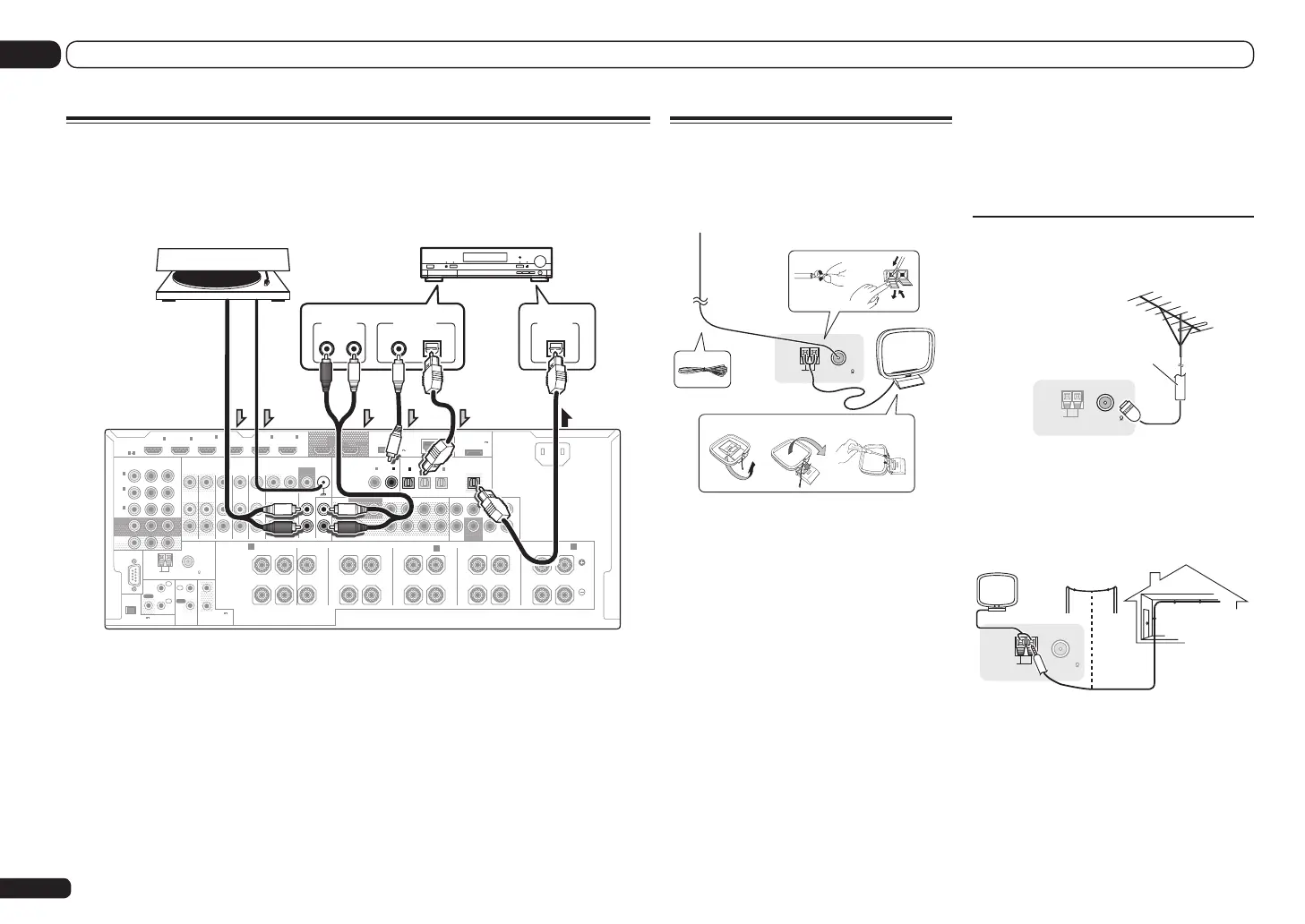
Connecting your equipment
Connecting other audio components
This receiver has both digital and analog inputs, allowing you to connect audio components for
playback.
When you set up the receiver you’ll need to tell the receiver which input you connected the compo-
nent to (see also The Input Setup menu on Operating Instructions in CD-ROM).
RS-232C
ZONE 2
IN IN IN IN
DVR/BDR
OUTOUT
ZONE 3
OUT
TV/SAT VIDEO
IN
PHONO
GND
SIGNAL
CD IN
DVD
OUT 1
(CONTROL)
OUT 2
PRE OUTMULTI CH IN
SUBWOOFER
12
COMPONENT VIDEO
YP
B
P
R
ASSIGNABLE
MONITOR
OUT
ZONE2
OUT
(
DVD
)
IN
1
(
DVR/
BDR
)
IN
2
(
VIDEO
)
IN
3
FRONT
CENTER
SURROUND SURR BACK F HEIGHTF WIDE
L
R
CENTERFRONTSURROUNDSURR BACK
(
CD
)(
DVD
)
COAXIAL
ASSIGNABLE
IN
1
IN
2
(
DVR/BDR
)(
TV/SAT
)
OPTICAL
ASSIGNABLE
IN
1
IN
2
IN
3
OUT
(
VIDEO
)
(
OUTPUT 5
V
0.1 A MAX
)
ADAPTER PORT
CU-RF100
DC OUTPUT
for WIRELESS LAN
(
10/100
)
LAN
(
OUTPUT
5 V
0.6 A MAX
)
FRONTCENTER
SURROUND
SURROUND BACK
RL RLRLRLRL
(
Single
)
(
Single
)
SPEAKERS
FRONT WIDE /
B
FRONT HEIGHT
A A
AC IN
FM UNBAL 75
AM LOOP
ANTENNA
(
OUTPUT 5 V
150 mA MAX
)
CONTROL
IR
OUT
IN
OUT
IN
1
IN
2
2
1
12 V TRIGGER
(OUTPUT 12 V
TOTAL 150 mA MAX)
VIDEO
AUDIO
MONITOR
OUT
HDMI
BD IN
(VIDEO)
IN
1
IN
2
IN
4
(DVD)
IN
5
(DVR/BDR)
IN
6
ASSIGNABLE
1 6
SUBWOOFER
DIGITAL OUT
COAXIAL OPTICAL
DIGITAL IN
OPTICAL
ANALOG
RL
AUDIO OUT
MD, DAT, etc.Turntable
Select one
! If your turntable has line-level outputs (i.e., it has a built-in phono pre-amp), connect it to the CD
inputs instead.
! You can’t hear HDMI audio through this receiver’s digital out jack.
 Loading...