En
23
02
Connecting your equipment
MULTI-ZONE setup
This receiver can power up to three indepen-
dent systems in separate rooms after you have
made the proper MULTI-ZONE connections.
Different sources can be playing in three zones
at the same time or, depending on your needs,
the same source can also be used. The main
and sub zones have independent power (the
main zone power can be off while one (or both)
of the sub zones is on) and the sub zones can
be controlled by the remote or front panel
controls.
Making MULTI-ZONE connections
It is possible to make these connections if
you have a separate TV and speakers for your
primary (ZONE 2) sub zone, and a separate TV
and a separate amplifier (and speakers) for your
secondary (ZONE 3) sub zone. You will also
need a separate amplifier if you are not using
the MULTI-ZONE setup using speaker terminals
(ZONE 2) on page 23 for your primary sub zone.
There are two primary sub zone setups possible
with this system. Choose whichever works best
for you.
MULTI-ZONE listening options
The following table shows the signals that can
be output to ZONE 2 and ZONE 3:
Sub
Zone
Input functions available
ZONE 2
DVD, TV/SAT, DVR/BDR, VIDEO,
HOME MEDIA GALLERY, iPod/USB,
CD, TUNER, ADAPTER PORT
(Outputs analog audio, composite video
and component video (SC-LX85 only).)
ZONE 3
DVD, TV/SAT, DVR/BDR, VIDEO,
HOME MEDIA GALLERY, iPod/USB,
CD, TUNER, ADAPTER PORT
(Outputs analog audio, composite
video.)
It is not possible to down-convert the audio
and video input signals from the HDMI input
terminals, digital input terminals (OPTICAL and
COAXIAL) and the COMPONENT VIDEO input
terminals and output them to ZONE 2/ZONE 3.
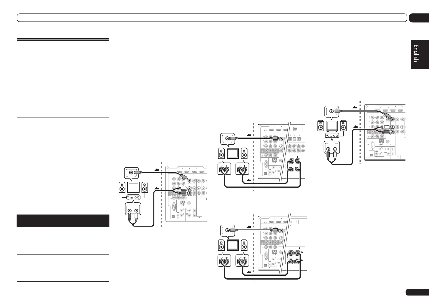
Basic MULTI-ZONE setup (ZONE 2)
1 Connect a separate amplifier to the
AUDIO ZONE 2 OUT jacks on this receiver.
You should have a pair of speakers attached to
the sub zone amplifier as shown in the follow-
ing illustration.
2 Connect a TV monitor to the VIDEO
ZONE 2 OUT jack on this receiver.
SC-LX85 only:
! COMPONENT VIDEO ZONE 2 OUT can be
used to output clear images.
! The GUI screen is not displayed if only the
COMPONENT VIDEO ZONE 2 OUT jack is
connected.
RS-232C
ZONE 2
IN IN
OUT
ZONE 3
OUT
TV/SAT VDVD
COMPONENT VIDEO
YP
B
P
R
ASSIGNABLE
MONITOR
OUT
ZONE2
OUT
(
DVD
)
IN
1
(
DVR/
BDR
)
IN
2
(
VIDEO
)
IN
3
CU-RF100
R
SPEAKERS
A
FM UNBAL 75
AM LOOP
ANTENNA
(
OUTPUT 5 V
150 mA MAX
)
CONTROL
IR
OUT
IN
OUT
IN
1
IN
2
2
1
12 V TRIGGER
(OUTPUT 12 V
TOTAL 150 mA MAX)
HDMI
BD IN
(VIDEO)
IN
1
IN
2
IN
4
ASSIGNABLE
1 6
RL
AUDIO IN
VIDEO IN
Sub zone (ZONE 2) Main zone
MULTI-ZONE setup using speaker
terminals (ZONE 2)
Either the surround back or the front wide
speaker terminals can be used as the
speaker terminals for ZONE 2. For details, see
Determining the speakers’ application on page
10.
1 Connect a pair of speakers to the
surround back or front wide speaker
terminals.
2 Connect a TV monitor to the VIDEO
ZONE 2 OUT jack on this receiver.
SC-LX85 only:
! COMPONENT VIDEO ZONE 2 OUT can be
used to output clear images.
! The GUI screen is not displayed if only the
COMPONENT VIDEO ZONE 2 OUT jack is
connected.
To use the front wide speaker terminals for ZONE
2:
PRE OUT
2
SURROUND SURR BACK F HEIGHT F WIDE FRONT
(
CD
)
D
)
SIGNABLE
1
IN
2
(
DVR/BDR
)(
TV/SAT
)
OPTICAL
ASSIGNABLE
IN
1
IN
2
IN
3
(
VIDEO
)
(
O
ADA
DC OUTPUT
r WIRELESS LAN
(
10/100
)
LAN
(
OUTPUT
5 V
0.6 A MAX
)
L RL
(
Single
)
FRONT WIDE /
B
RS-232C
ZONE 2
OUT
ZONE 3
OUT
COMPONENT VIDEO
YP
B
P
R
ASSIGNABLE
MONITOR
OUT
ZONE2
OUT
(
DVD
)
IN
1
(
DVR/
BDR
)
IN
2
(
VIDEO
)
IN
3
CU-RF100
FM UNBAL 75
AM LOOP
ANTENNA
(
OUTPUT 5 V
150 mA MAX
)
CONTROL
IR
OUT
IN
OUT
IN
1
IN
2
2
1
12 V TR
(OUTPUT
TOTAL 15
HDMI
(VID
IN
1
IN
2
IN
ASSIGNABLE
1 6
VIDEO IN
RL
Sub zone (ZONE 2)
Main zone
To use the surround back speaker terminals for
ZONE 2:
H IN
L
R
ACK
SURROUND BACK
L RL
(
Single
)
A
AC IN
RS-232C
ZONE 2
OUT
ZONE 3
OUT
COMPONENT VIDEO
YP
B
P
R
ASSIGNABLE
MONITOR
OUT
ZONE2
OUT
(
DVD
)
IN
1
(
DVR/
BDR
)
IN
2
(
VIDEO
)
IN
3
CU-RF100
FM UNBAL 75
AM LOOP
ANTENNA
(
OUTPUT 5 V
150 mA MAX
)
CONTROL
IR
OUT
IN
OUT
IN
1
IN
2
2
1
12 V TR
(OUTPUT
TOTAL 15
HDMI
(VID
IN
1
IN
2
IN
ASSIGNABLE
1 6
VIDEO IN
RL
Sub zone (ZONE 2)
Main zone
Secondary MULTI-ZONE setup
(ZONE 3)
1 Connect a separate amplifier to the
AUDIO ZONE 3 OUT jacks on this receiver.
You should have a pair of speakers attached to
the sub zone amplifier as shown in the follow-
ing illustration.
2 Connect a TV monitor to the VIDEO
ZONE 3 OUT jack on this receiver.
RS-232C
ZONE 2
IN IN
OUT
ZONE 3
OUT
TV/SAT VDVD
COMPONENT VIDEO
YP
B
P
R
ASSIGNABLE
MONITOR
OUT
ZONE2
OUT
(
DVD
)
IN
1
(
DVR/
BDR
)
IN
2
(
VIDEO
)
IN
3
CU-RF100
R
SPEAKERS
A
FM UNBAL 75
AM LOOP
ANTENNA
(
OUTPUT 5 V
150 mA MAX
)
CONTROL
IR
OUT
IN
OUT
IN
1
IN
2
2
1
12 V TRIGGER
(OUTPUT 12 V
TOTAL 150 mA MAX)
HDMI
BD IN
(VIDEO)
IN
1
IN
2
IN
4
ASSIGNABLE
1 6
RL
AUDIO IN
VIDEO IN
Sub zone (ZONE 3) Main zone
Secondary MULTI-ZONE setup using
speaker terminals (ZONE 3)
You must select 5.1ch + ZONE 2+3 in Speaker
system setting to use this setup.
1 Connect a pair of speakers to the front
wide speaker terminals.
You should have a pair of speakers attached to
the sub zone amplifier as shown in the follow-
ing illustration.
 Loading...