7-6
PAGE
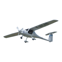
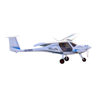
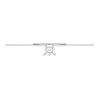
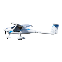
ALPHA Trainer LSA
Pilot Operating Handbook
POH-162-00-40-001
PAGE REV. 0
SECTION 7
AIRPLANE DESCRIPTION
The wings attach with shear pins to bushes at the fuselage root ribs. Each
wing half can be optionally equipped with glider type electric airbrakes.
7.2.3 EMPENNAGE
The empennage consists of a horizontal stabilizer, a single piece elevator, a
vertical fin and a rudder. All of the empennage components are convention-
al spar (shear web) and skin construction.
The horizontal stabilizer is attached to an aluminum bracket that is pivoted
to the vertical stabilizer and can be removed. The shell of the horizontal tail
is designed as CFRP sandwich. The horizontal tail is attached to an alumi-
num bracket at the back C-spar and a self locking bolt at the location of the
front C-spar.
The elevator is designed as a bottom surface supported hinged flap. The
elevator is actuated through a pushrod connected to the elevator control
bracket. The elevator shell is designed as a 1-cell CFRP sandwich shell.
The elevator is hinged in maintenance-free bushings mounted on stainless
steel brackets at the stabilizer rear spar and bottom shell. Counterbalance
weights are integrated into the elevator tips.
The vertical fin is designed to be one part with the tail fuselage, made of
carbon honeycomb sandwich with carbon spars. The bending moment is
carried by one C-type spar which is reinforced by CFRP tapes at the flanges.
The rudder is designed as a centrally supported hinged flap. The rudder
shell is designed as single-cell GFRP sandwich shell. The rudder is hinged
in two maintenance-free spherical plain bearings. Balancing weights are
mounted at the front end of the rudder.