7-7
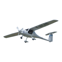
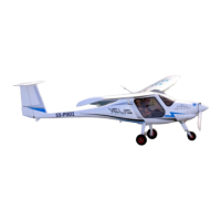
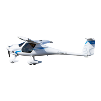
ALPHA Trainer LSA
Pilot Operating Handbook
POH-162-00-40-001
PAGE REV. 0
PAGE
SECTION 7
AIRPLANE DESCRIPTION
7.3 FLIGHT CONTROL SYSTEM
The aircraft uses conventional flight controls for ailerons, elevator and rud-
der. The control surfaces are pilot controlled through either of two control
sticks positioned centrally in front of each pilot. The location and design of
the control sticks allow easy, natural use by the pilots. The control system
uses a combination of push rods, cables and bell cranks for control of the
surfaces.
Pitch trim is available through an electric button located on the instrument
panel.
7.3.1 ELEVATOR CONTROL SYSTEM
The sticks are mounted on a common lateral rod which actuates the elevator
longitudinal pushrod, running the length of the fuselage behind the cockpit
control levers. A bell-crank is located on the bottom side of the vertical fin
and can be inspected through a provision in the vertical stabilizer end-rib.
The hook-up to the elevator is via a U-member which conforms to the shape
of the elevator. In case the horizontal tail plane is removed the U-member
remains attached to the fuselage whereas the elevator remains attached
to the horizontal stabilizer. There are no cables in the pitch control system.
7.3.2 AILERON CONTROL SYSTEM
Roll control is achieved by torsional activation of flaperon control surfaces
via an all-pushrod mechanisms. A conventional center control stick is avail-
able to each pilot. The sticks are mounted on a common lateral rod which
actuates the elevator longitudinal pushrod. There is a bell-crank located on
the bottom of the fuselage behind the seats which provides dierential mo-
tion. The flap handle is connected to this bell-crank, allowing for symmetric
displacement of flaperons.
7.3.4 RUDDER CONTROL SYSTEM
Rudder pedals are available to each pilot and are adjustable in-flight in a
fore-aft sense. Metal cables in teflon-coated bowdens run from the individual
pedal to bellcranks located behind the seats and below the cargo compart-
ment floor. Single cables run from the cable junction backwards and are at-
tached directly to the rudder. The tension of the cables is adjusted with cable
tensioners and rudder neutralisation is achieved by means of two retaining
springs attached to the bellcranks junctions.