2322
Part# Description
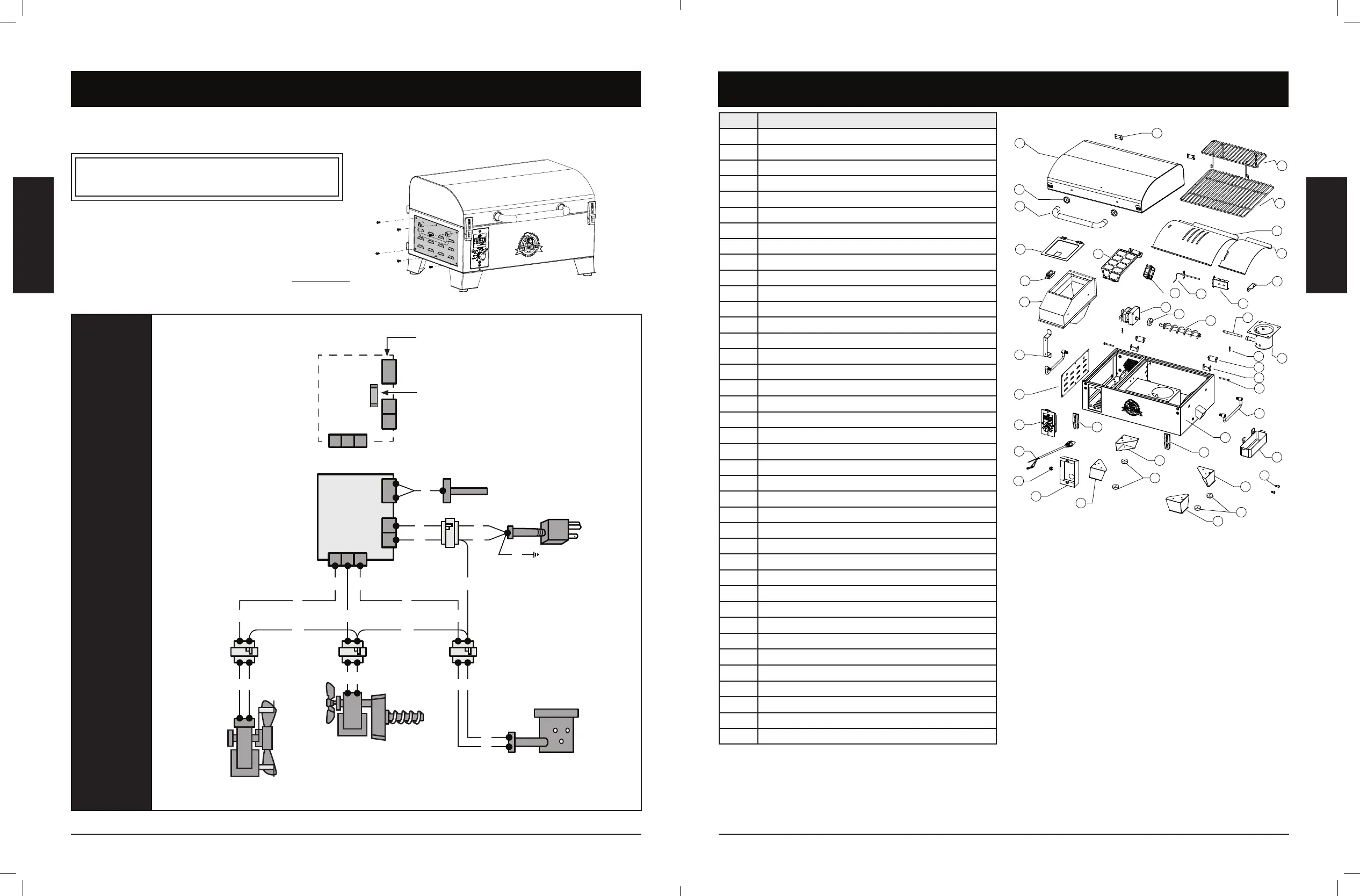
1 Lid (x1)
2 Bezel with Bolt (x2)
3 Lid Handle (x1)
4 Lid Hinge (x2)
5 Upper Cooking Grate (x1)
6 Cooking Grid (x1)
7 Flame Broiler™ Main Plate (x1)
8 Flame Broiler™ Slider (x1)
9 Flame Broiler™ Hanger Bracket (x1)
10 Grill Probe Shield (x1)
11 Grill Probe (x1)
12 Combustion Fan (x1)
13 Auger Motor (x1)
14 Nylon Bushing (x1)
15 Auger Fighting Assembly (x1)
16 Igniter (x1)
17
Burn Pot (x1)
18
R Pin (x2)
19
Hinge B (x2)
20
Body Hinge (x2)
21
Pin (x2)
22
Side Handle (x2)
23 Grease Cup (x1)
24 Firebox / Body (x1)
25 Hasp (x2)
26 Foot A (x2)
27 Foot Gasket (x4)
28 Foot B (x2)
29 Control Board Protective Box (x1)
30
Rubber Ring (x1)
31
Power Cord (x1)
32
Control Board (x1)
33
Hopper Access Panel (x1)
34
Power Cord Bracket (x1)
35
Hopper Safety Screen (x1)
36
Hopper Box Housing (x1)
37 Hopper Lid Switch (x1)
38 Hopper Lid (x1)
39 Grease Cup Screw (x2)
The Digital Control Board system is an intricate and valuable piece of technology. For protection from power surges and electrical
shorts, consult the wire diagram below to ensure your power source is sufficient for the operation of the unit.
PB – ELECTRIC REQUIREMENTS
110-120 V, 60 Hz, 220 W, 3-PRONG GROUNDED PLUG
: Electrical components, passed by product safety testing and certification services, comply
with a testing tolerance of ± 5-10 percent.
LOCATE AND REMOVE
THE SIX SCREWS
OF ACCESS PANEL ON
LEFT SIDE OF UNIT
FUEL INPUT ATING:
05 / 11 /
INDEX
P
P
G
Y
Y
Y P
K
S
W
K
W
G
W
W
W
G G
WW
W
W
Y Y
IGNITER ASSEMBLY /
HD CARTRIDGE HEATER
110120 , 200 ,
0375” 5000”
BURN POT
IGNITER
DRAFT FAN
110120 , 60 z,
1
GROUNDED
POWER CORD
1, 105°/221°,
183
AUGER MOTOR
& FEED SYSTEM
110120 , 60 z,
2
GROUND
GRILL PROBE
R
R R
GRILL PROBE
SPADE CONNECTORS
FAST-BLOW
FUSE
DIGITAL CONTROL BOARD
3
2
1
4
5
6
7
8
9
10
1 1
12
13
14
15
16
17
18
19
20
21
22
23
25
26
27
28
29
32
33
34
36
37
38
24
30
31
27
25
28
26
35
39
 Loading...