ENGLISH
24
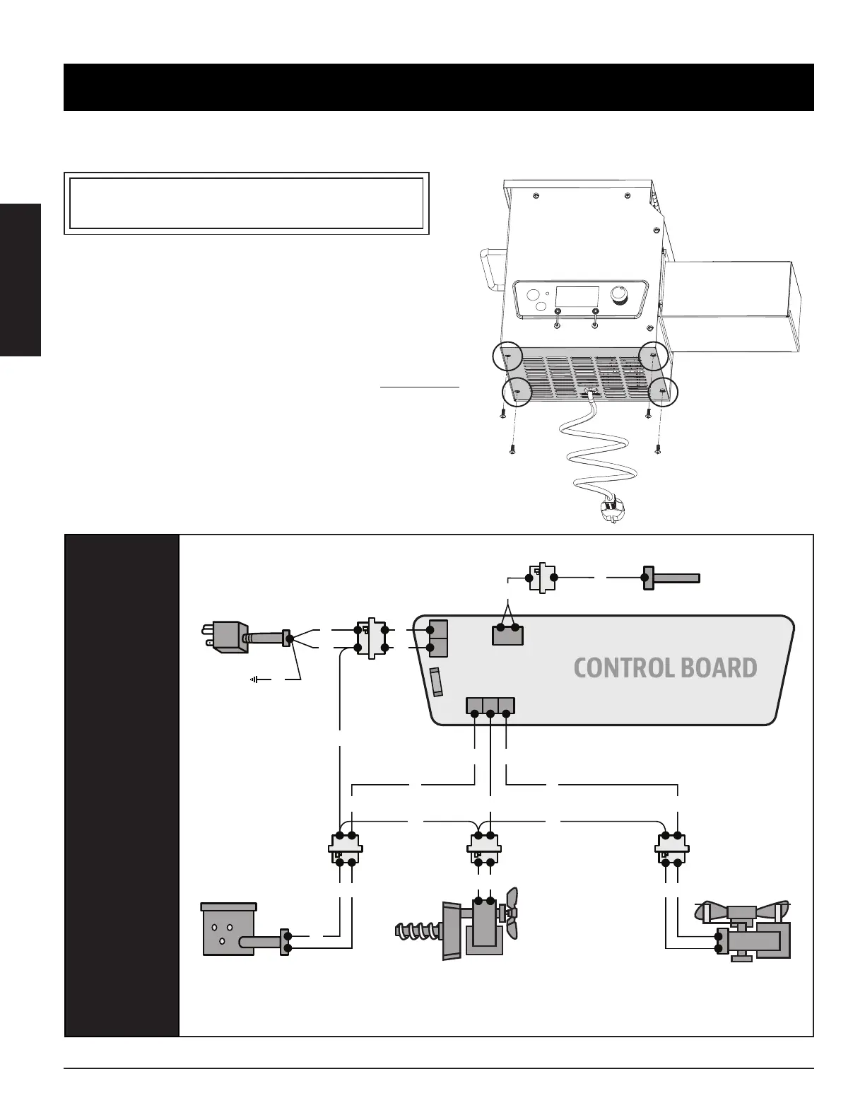
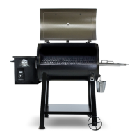
The Digital Control Board system is an intricate and valuable piece of technology. For protection from power surges and electrical
shorts, consult the wire diagram below to ensure your power source is sufficient for the operation of the unit.
PB – ELECTRIC REQUIREMENTS
110-120 V, 60 Hz, 250 W, 3-PRONG GROUNDED PLUG
: Electrical components, passed by product safety testing and certification services, comply
with a testing tolerance of ± 5-10 percent.
LOCATE AND REMOVE
THE FOUR SCREWS
OF ACCESS PANEL ON
UNDERSIDE OF UNIT
FUEL INPUT
RATING:
173 /
078 /
INDEX
P
P
R
Y
Y
YP
K
W
W
G
W
W
W
R R
WW
W
L
W
YY
K
W
S
IGNITER ASSEMBLY /
HD CARTRIDGE HEATER
120, 200,
0375” 5000” / 95 127
BURN POT
DRAFT FAN
120, 60 z,
1
GROUNDED
POWER CORD
AUGER MOTOR
& FEED SYSTEM
120, 60 z,
2
GROUND
GRILL
PROBE
GRILL PROBE
CONNECTOR
FAST-BLOW FUSE