11
4.
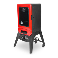
MOUNTING SUPPORT PANELS TO
FOUR LEGS
Parts Required:
2 x Support Panel (#19)
1 x Right Front Leg (#22)
1 x Left Front Leg (#21)
1 x Right Rear Leg with Wheel Assembly (#18)
1 x Left Rear Leg with Wheel Assembly (#20)
8 x #10-24*1/2”Screw (#C)
Installation:
• Mount Support Panel (#19)to the Right
Front Leg (#22)and Right Rear Leg with
Wheel Assembly (#18) using 4 x
#10-24*1/2”Screws (#C)as Fig.4 shown.
• Mount Support Panel (#19)to Left Front
Leg (#21)and Left Rear Leg with Wheel
Assembly (#20)using 4 x
#10-24*1/2”Screws (#C)as Fig.4 shown.
Fig.4
5.
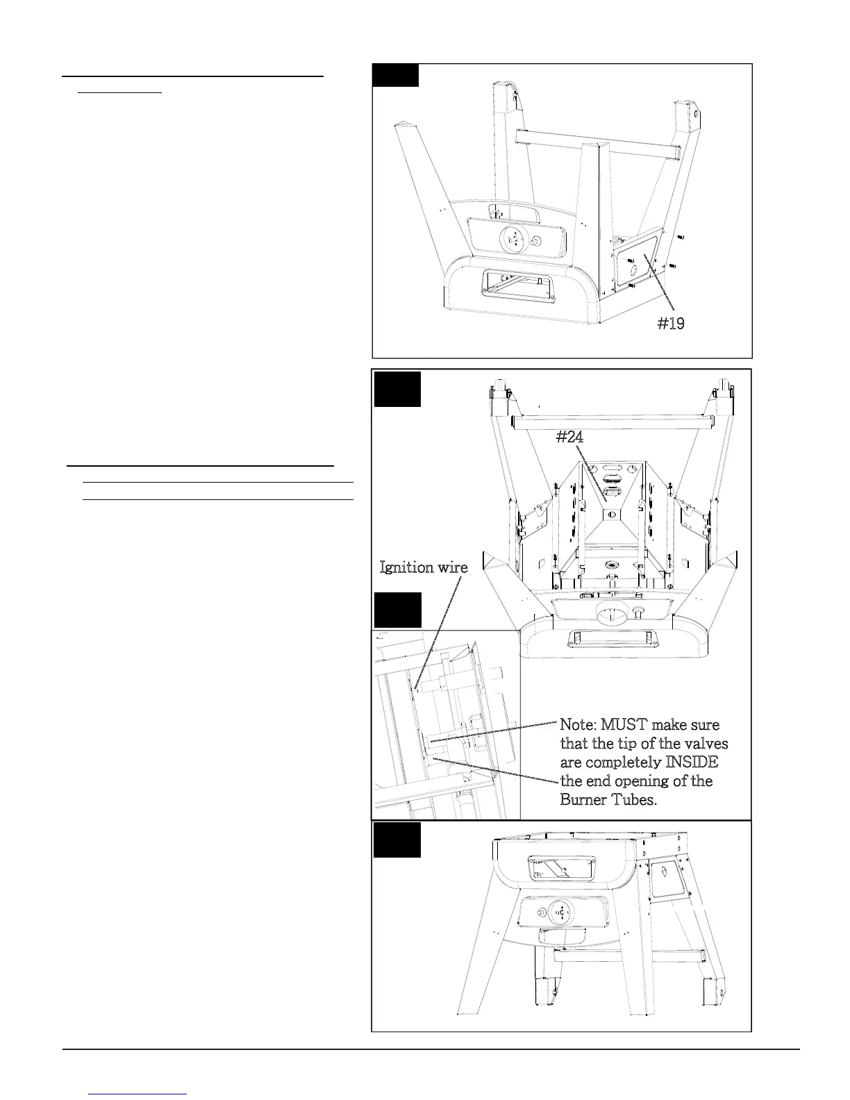
MOUNTING BURNER CHAMBER
ASSEMBLY TO THE BOTTOM AREA OF
LOWER SMOKER CABINET ASSEMBLY
Parts Required:
1 x Burner Chamber Assembly (#24)
1 x Lower Smoker Cabinet with Control
Panel Assembly (#14)
4 x #10-24*1/2”Screw (#C)
Installation:
• Attach ignition wire onto the pin end of
the Igniter on Control Panel.
Mount Burner Chamber Assembly (#24) to
the bottom area of Lower Smoker Cabinet
with Control Panel Assembly (#14) using 4
x #10-24*1/2”Screws (#C)as Fig.5.1 &
Fig.5.2 shown.
Fig.5.1
#19
-
--
--
----
--
Note: MUST make sure
t
hat the tip of the valves
a
re completely INSIDE
t
he end opening of the
B
urner Tubes.
-
-
-
-
-
-
-
-
-
-
-
-
-
-
-
-
-
-
-
-
-
-
-
--
-
--
--
--
--
-
---
-
--
--
-
Note: Turn the Lower Smoker Cabinet with
Control Panel and Legs Assembly Right
Side Up as Fig.5.3 shown and tighten all
screws now.
Fig.5.2
Ignition wire
-
-
-
-
-
--
-
-
-
-
-
--
-
-
-
-
-
-
-
#24
---
-
-
-
---
--
Fig.5.3
 Loading...