MODEL SG6H FRYER INSTALLATION
L20-332, rev. 1 (05/11) 9
OFF
ON
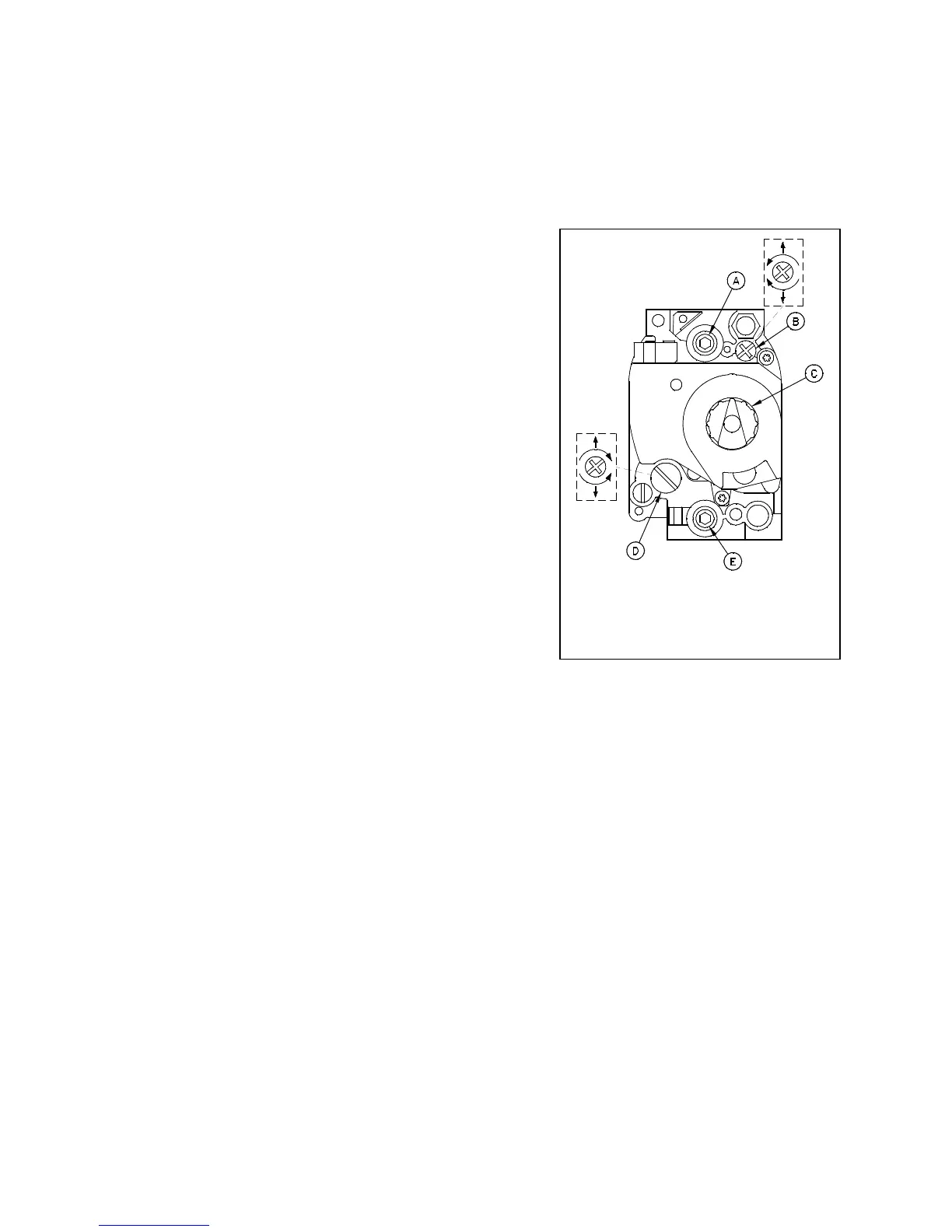
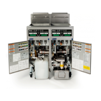
) Burner Pressure Tap
B) Pilot Adjustment Screw Cap
C) ON/OFF Knob
D) Burner Pressure Adjustment Screw Cap
E) Inlet Pressure Tap
1.8.3. PILOT FLAME ADJUSTMENT
Perform this procedure with the pilot lit.
Note: This procedure requires the use of a DC microammeter.
1. Connect the DC microammeter between the flame
sensor terminal and the flame sensor lead.
Observe proper polarity: if the meter needle goes
below 0, reverse the leads. The current reading
must be 1.0 A or greater, (0.15 A or greater for
CE units).
2. Adjust the current reading to the required level by
adjusting the pilot flame. Remove the pilot
adjustment screw cap screw to expose the pilot
adjustment screw. Turning the pilot adjustment
screw clockwise will decrease the size of the pilot
flame and flame sense current. Turning the pilot
adjustment screw counterclockwise will increase
the pilot flame size and the flame sense current.
3. Rotate the screw in the direction needed to
achieve a reading of 1.0 A or greater, (0.15 A or
greater for CE units).
Note: Allow 3 to 5 minutes between flame
adjustments to allow the reading to stabilize.
4. Once the pilot flame has been adjusted properly,
replace the pilot adjustment screw cap screw and
remove the microammeter.