ATR 421 - Manuale uso 59
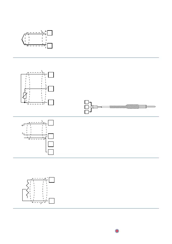
Ingresso analogico AI1
11
12
AI1
TC
Shield/Schermo
Per termocoppie K, S, R, J, E, N.
• Rispettare la polarità
• Per eventuali prolunghe utilizzare cavo com-
pensato e morsetti adatti alla termocoppia
utilizzata (compensati)
• Quando si usa cavo schermato, lo schermo deve
essere collegato a terra ad una sola estremità
11
12
13
AI1
Shield/Schermo
PT/NI100
Per termoresistenza PT100
• Per il collegamento a tre li usare cavi della
stessa sezione.
• Per il collegamento a due li cortocircuitare i
morsetti 11 e 13.
• Quando si usa cavo schermato, lo schermo deve
essere collegato a terra ad una sola estremità
11
12
13
RED/ROSSO
WHITE/BIANCO
RED/ROSSO
11
12
17
AI1
V
mA
+24V
Shield/Schermo
Per segnali normalizzati in corrente e tensione
• Rispettare la polarità
• Quando si usa cavo schermato, lo schermo deve
essere collegato a terra ad una sola estremità
Ingresso analogico AI2
15
16
AI2
FEEDBACK
POT.
Shield/Schermo
Per potenziometro di retroazione su valvole
motorizzate
• Resistenza massima 150 KΩ.
• Quando si usa cavo schermato, lo schermo
deve essere collegato a terra ad una sola estre-
mità