20
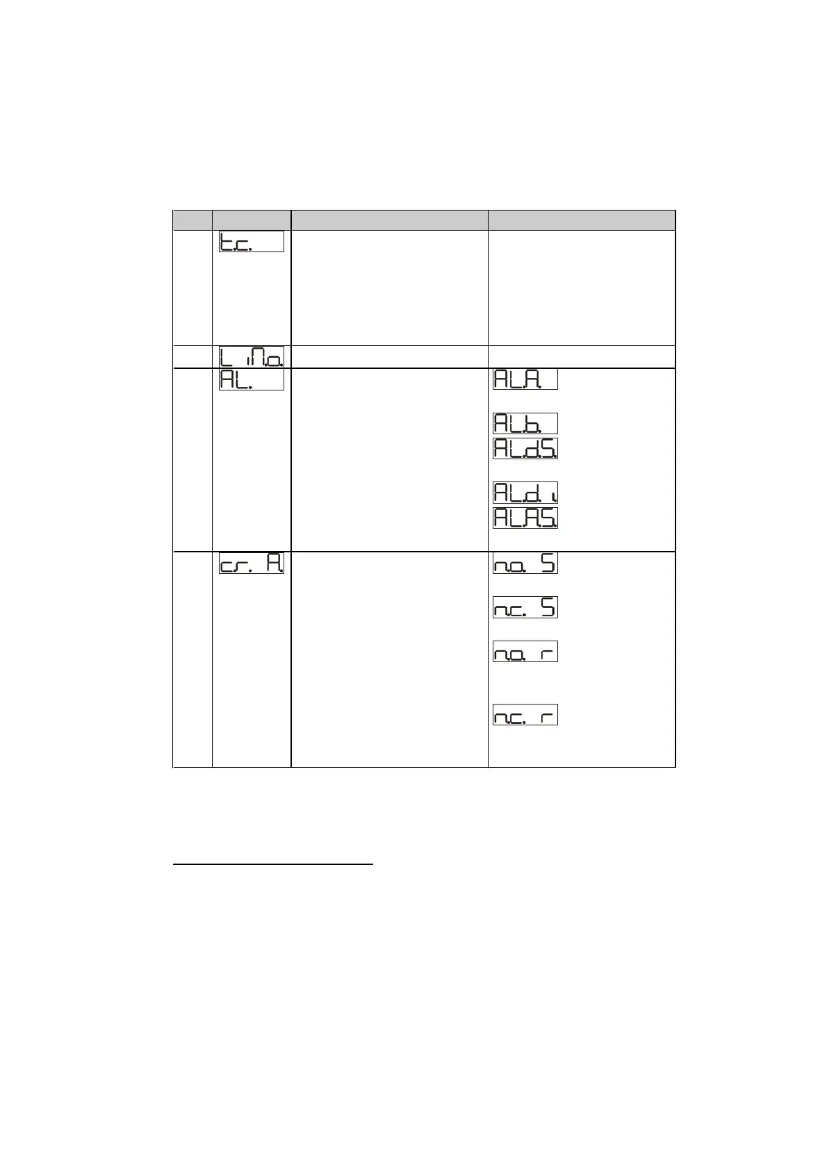
No. Display Description Range
16 Cycle time (for PID on
contactors 10/15sec., for
PID on SSR 1sec.) or
servomotor time (value
declared by
manufacturer)
1-300 seconds
17 % Limit of output power 10-100 %
18 Alarm configuration
Alarm is related to
setpoint 2.
: absolute
related to process
: band alarm
: deviation
High
: deviation Low
: absolute
related to setpoint 1
19 State of contact for alarm
output
:
N.O., active at start
:
N.C., active at start
:
N.O. active at alarm
treshold
1
:
N.C., active at alarm
treshold
1
1
At starting the output is desabled in case of any alarm condition
of the controller. Once that alarm has been solved, the output will
be activated only if the alarm should happen again.