22
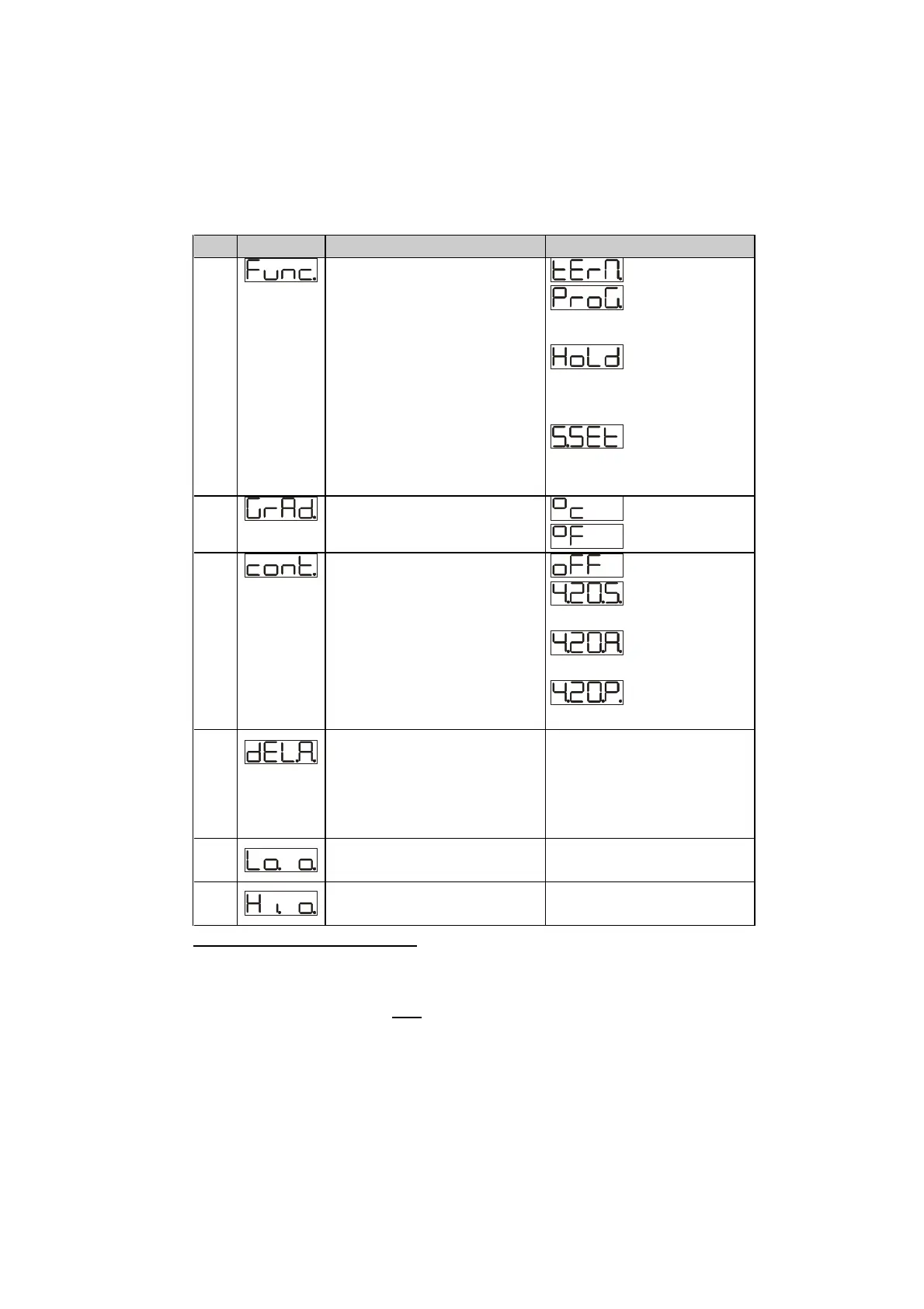
No. Display Description Range
27 Select type of operating
for the controller
: Controller
: Cycle
programmer (see 5.7)
:digital input
active to stop reading of
sensor input (see 5.8)
: digital input to
select setpoint for
control
2
.
28 Type of degrees
: centigrades
: Fahrenheit
29 Retransmission of
process or setpoint value
as signal 4..20mA
(select Jumper JP5 and
JP7)
Parameters 31 and 32 fix
the limits of scale
:desabled
:
retransmission Set1
:
retransmission Set2
:
retransmission Process
30 Output delay
[state of relay, valve
Open/Close, SSR, output
4-20mA ]
PID control is excluded
0-5000 milliseconds
31 Lower limit output 4-
20mA
-999…+9999 digits
32 Upper limit output 4-
20mA
-999…+9999 digits
2
When pins 3 and 2 are shortcircuited, control action of ATR241
refers to Setpoint2, usually main setpoint is Setpoint1. This
function is not available for PT100 and NI100 and it excludes
alarm function.