35
Uscite Out2 a Relè / SSR / Continua 4…20mA
Portata contatti 3A/250V~ per carichi
resistivi
Funzionamento in Configurazione:
• Relè di allarme (con parametro 1
configurato )
• Relè CHIUDI valvola (con
configurazione servo apri – chiudi)
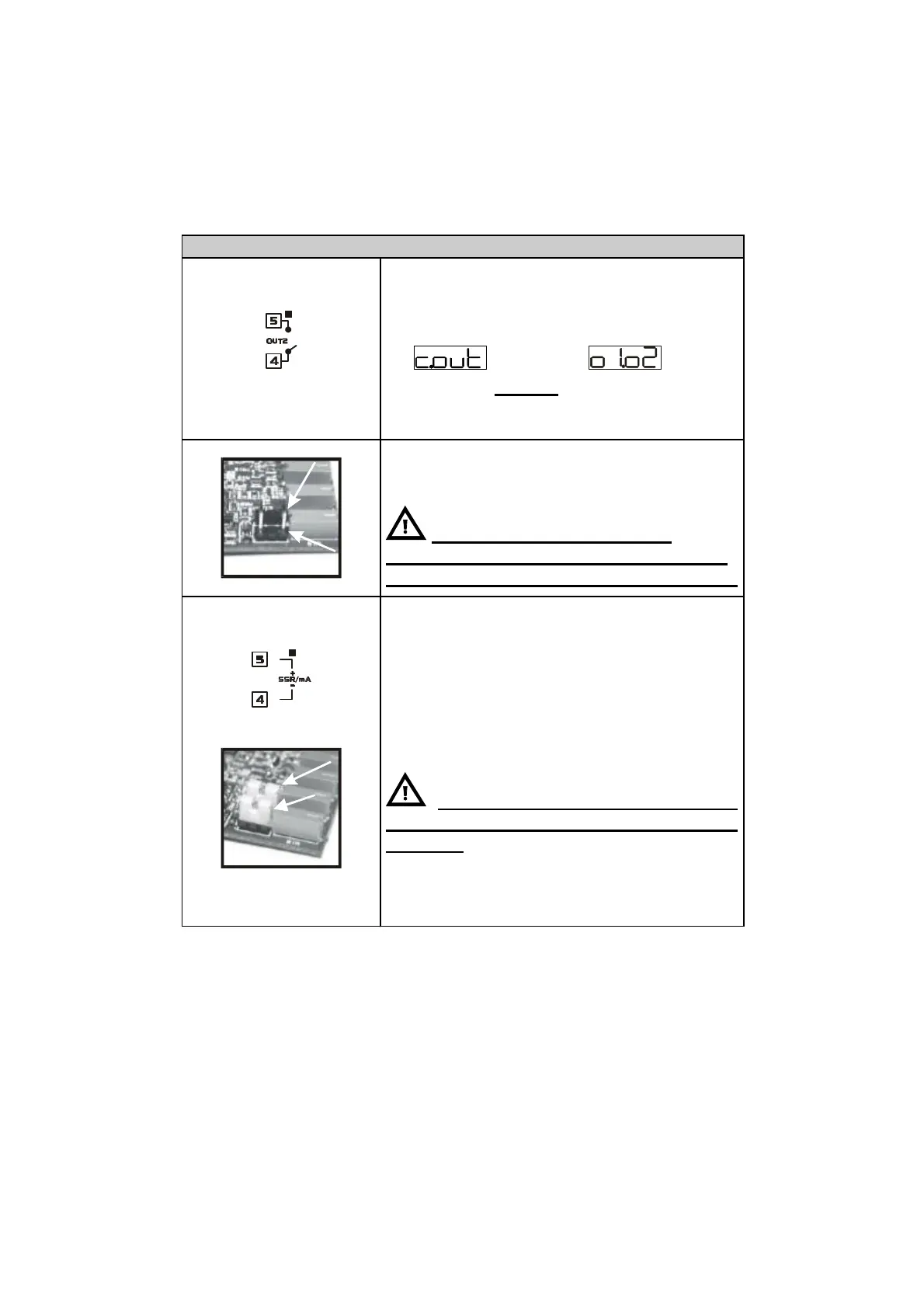
• Per Out2 selezionata come uscita relè
togliere i jumper JP5 e JP7 come
indicato in figure.
connettere un carico senza
togliere i jumper significa danneggiare
in modo irreversibile il termoregolatore.
Portata 12V/30mA
• Uscita comando (con configurazione
SSR)
• Allarme 1 (con comando su OUT1)
• Uscita continua 4-20mA configurabile
da parametri come comando o
ritrasmissione del processo o dei
setpoint.
Selezionare JP5 e JP7 (inserire
entrambi) per utilizzare l’uscita SSR o
continua