11
In measurement modes, the measured constant voltage (VDC) value or the alternating voltage
(VAC) value of the cable network is displayed at the top of the screen.
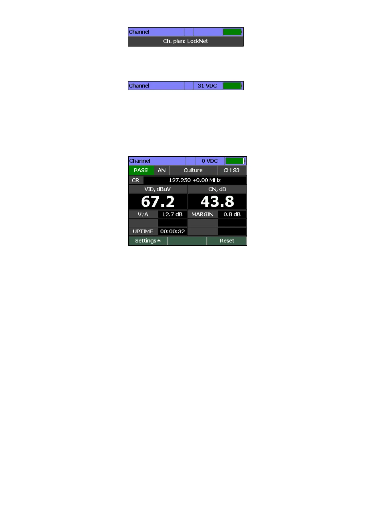
4.3.2 Channel Measurement Mode
In this mode, the measurement of TV channel parameters and the voltage level applied to the
input of the device is performed. The view of the screen for a channel with analog modulation is
shown in Figure 4.2.
The following information is shown on the screen:
• express-test result: PASS/FAIL if a quick scan is on (Section 4.4.3);
• Name and number of the channel;
• CR: video level frequency and offset;
• VID: video level;
• CN: signal/noise value;
• V/A: video level to sound level ratio;
• MARGIN: signal/noise value margin;
• UPTIME: measuring time.
If a quick check of parameters is enabled (Section 4.4.3), the parameter with failed value is
highlighted in red.
To measure the signal-to-noise ratio, the Analyzer carries out measurements at the point with the
lowest level of useful components of the radio-frequency signal in the channel band. The
frequency of noise measurement is determined automatically by searching for the best possible
point in the frequency range with the video level offset from - 1.5 to 6.0 MHz.
The screen view for a channel with digital modulation is shown in Figure 4.3.