12
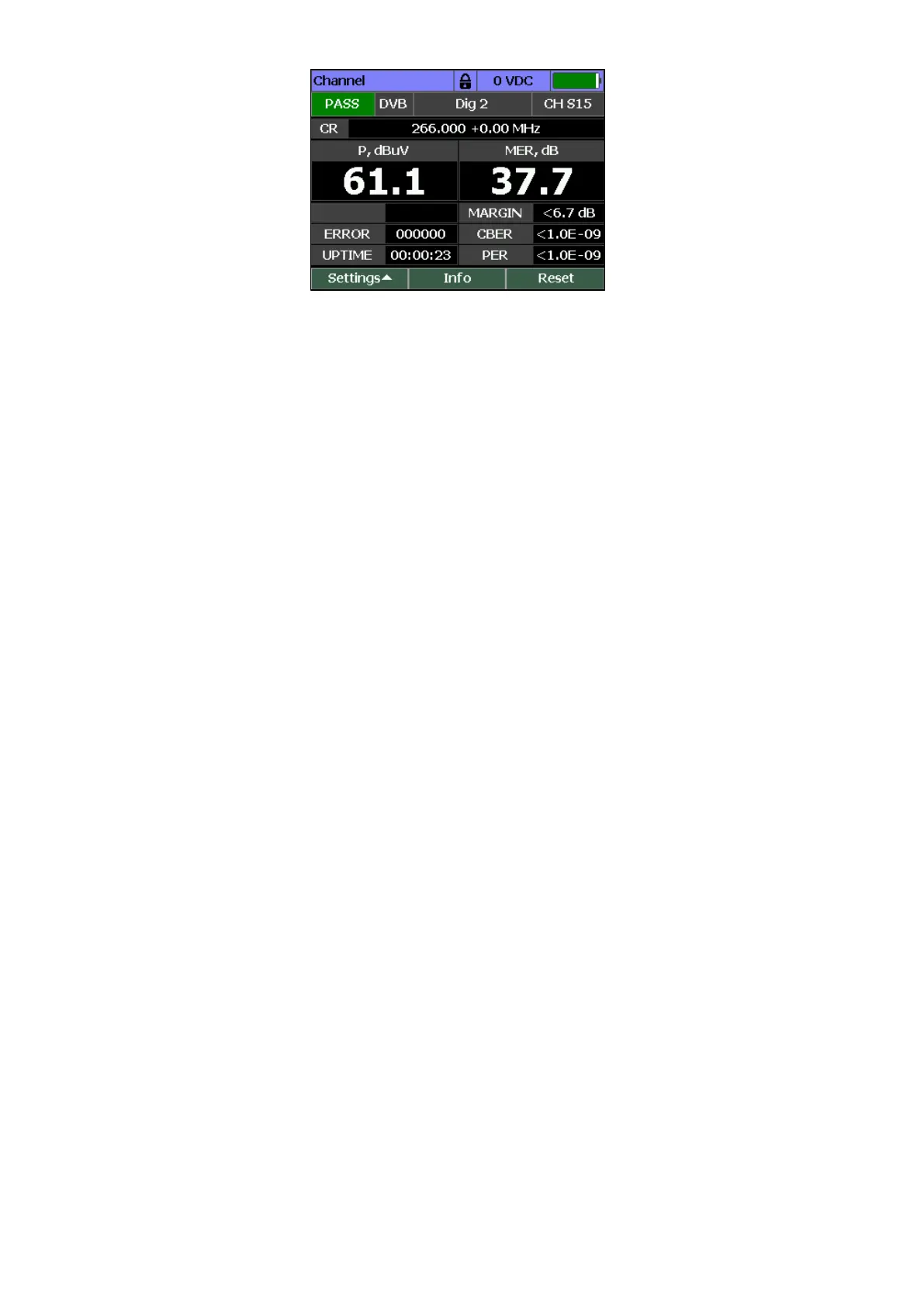
Figure 4.3
The following information is presented on the screen:
• express-test result: PASS/FAIL if a quick scan is on (Section 4.4.3);
• channel synchronization icon;
• name and number of the channel;
• CR: channel frequency and offset;
• P: channel power;
• MER value;
• MARGIN: MER margin;
• ERROR: the number of unrepaired packets of the MPEG stream;
• UPTIME: parameter measurement time;
• CBER: BER channel value (preBER);
• PER: MPEG stream Packet Error Ratio.
Input voltage level measurement is carried out in the range from 10 to 100 V. The typical value of
absolute measurement accuracy shall not exceed ± 1.5 V. The value of voltage level measured at
the input connector of the device is displayed at the top line of the screen. If the voltage is
constant, the value is displayed as 50VDC. If the voltage is altering, the value is displayed as
50VAC.
Tune to the desired channel using «◄» and «►» to measure channel parameters. In case of
working without a channel plan, you can tune to any channel according to the selected Channel
template (Section 4.5) using «◄» and «►». If there is a TV signal, the Analyzer automatically
determines the channel type. When working with the selected channel plan (Section 4.4.2), re-
tuning is carried out through channels from this plan.
4.3.3 Scan Measurement Mode
In this mode the screen displays signal levels as a bar-graph. It is presented in Figure 4.4: