14
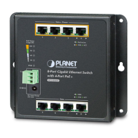
Step 4: Align two wall type holes at the bottom of the PoE Ethernet Switch with
screws and hang the PoE Ethernet Switch on it.
51V DC
Figure 3-3: PoE Ethernet Switch Wall Mount Installation
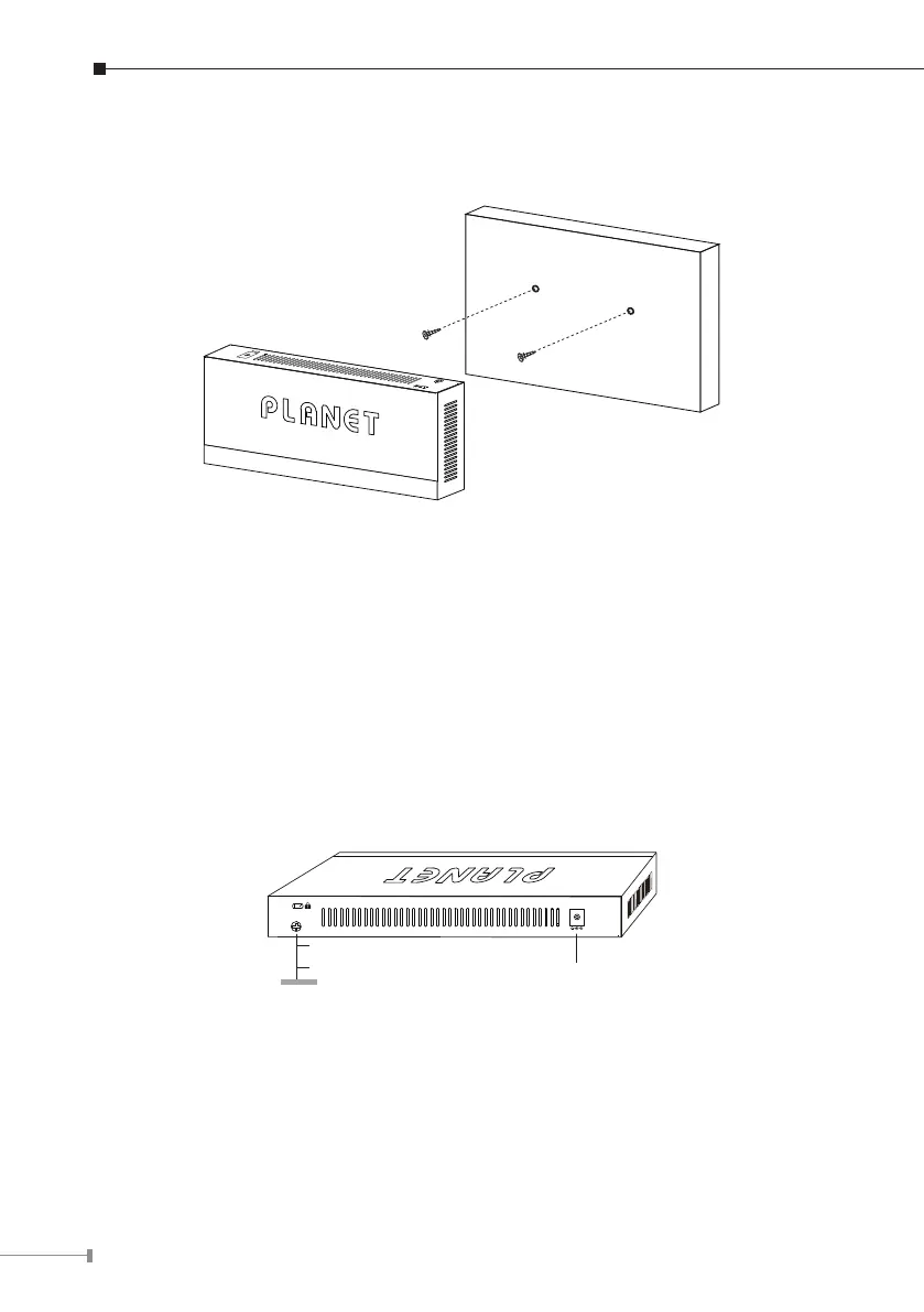
3.4 Protective Grounding Cable Installation
The proper connection of the protective grounding cable is not only for quickly
releasing the over voltage and over current from lightning strike, it also provides
necessary protection for users’ body security.
3.4.1 Installation Environment with Grounding Bar
Connect one end of the protective grounding cable to the binding post on the
grounding bar and x the screws, as shown in Figure 3-4.
51V DC
(1) AC Power Input Jack
(3) Protective Grounding Cable
(2) Binding Post
(2)
(3)
(4)
(1)
Figure 3-4: Grounding Bar Installation
 Loading...