5
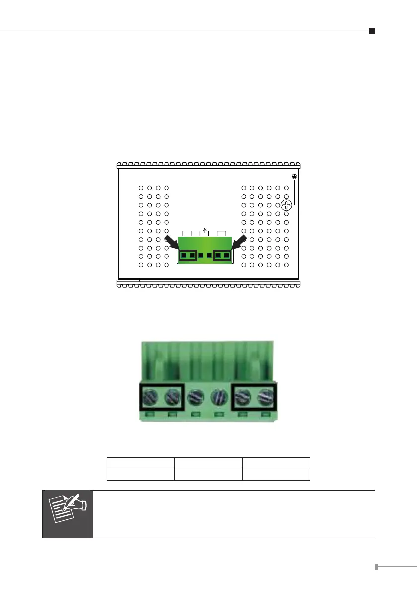
3. Wiring the Power Inputs
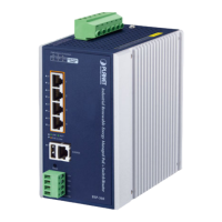
The Upper Panel of the LRP Managed Switch indicates a DC inlet power socket
and consists of one terminal block connector within 6 contacts. Please follow the
steps below to insert the power wire.
1.Insert positive/negative DC power wires into contacts 1and 2 for Power 1 or 5,
and6forPower2.
LRP-422CST: DC 48~56V
Input DC 48-56V
DC1
DC2
Fault
Figure 3-1: LRP-422CST Upper Panel
2.Tightenthewire-clampscrewsforpreventingthewiresfromloosening.
1 2 3 4 5 6
V1+ V1- V2+ V2-
Power 1 Power 2
Positive (+) Pin Negative (-) Pin
LRP-422CST Pin 1/5 Pin 2/6
The wiregauge forthe terminal blockshould be inthe rangefrom
12to24AWG.