22
10 Hydraulic diagrams
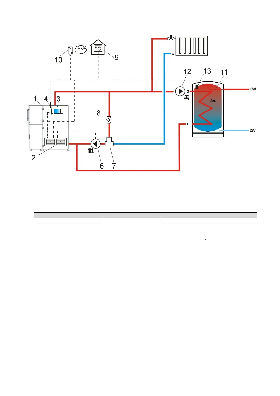
10.1 Schema 1
Fig. 10 Diagram with thermostatic three-way valve which protects the temperature of return
water
1
, where:1 – boiler with feeder, 2 – ecoMAX810P3-L regulator, 3 – regulator control panel, 4 –boiler
temperature sensor, 6 – central heating cycle pump, 7 – thermostatic three-way valve, 8 –throttle (poppet)
valve, 9 – room thermostate, 10 – temperature sensor-weather, 11 – domestic hot water tank, 12 –
domestic hot water pump, 13 – domestic hot water temperature sensor.
RECOMMENDED SETTINGS:
Short operation description: CH pump (6) and and HUW pump (12) start once the boiler
temperature has exceeded CH pump activation temperature (usually: 40 C). In case the water,
which flows to the boiler is cold, thermostatic valve (7) closes. It causes the flow of boiler water
in short circuit: boiler (1) – throttle valve (8) - thermostatic valve (7) – pump (6). Thermostatic
valve (7) opens upon increase of boiler return temperature and directs boiler water to CH system.
Once the temperature measured by the sensor (13) has dropped to below Pre-set HUW
temperature, HUW pump (12) starts operation. HUW pump (12) stops upon completed filling of
HUW container (11), i.e. when the temperature measured by the sensor (13) is equal to Pre-set
HUW temperature.
1
The presented hydraulic diagram does not replace the central heating system design and is
provided solely for the purposes of demonstration!

 Loading...