POCLAIN HYDRAULICS
38 DOC-REPAIR-MS02-MS18-FR-EN 677777845L
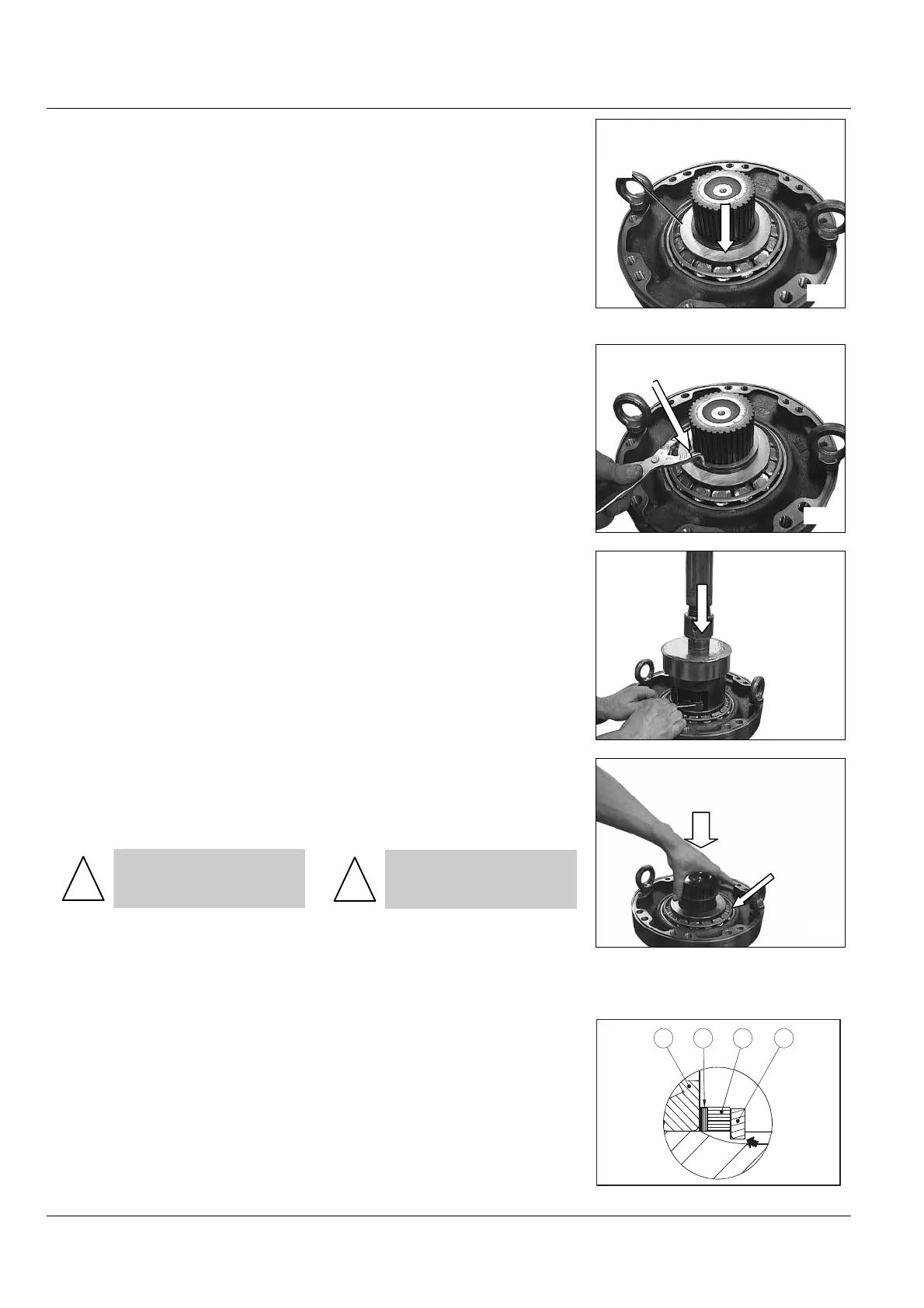
• Relâcher l'effort F, et monter la
bague d’appui (076)
• Release the F force, and install
the thrust ring (076)
• Monter l’anneau d’arrêt (077) en
utilisant une pince à anneaux d’arrêt
extérieurs
• Remove the snap ring (077) us-
ing external snap ring pliers
• Appliquer l’effort F (voir tableau
page 75) sur le roulement (074),
puis mesurer le jeu entre la bague
d’appui (076) et l’anneau d’arrêt
(077).
• Déterminer le calage (075) afin
d'obtenir le couple de rotation (C)
correspondant (voir tableau page
75). (valeur approximative du ca-
lage = mesure + S)
• Apply the F force (see table
page 75) on the bearing (074), then
measure the clearance between the
thrust ring (076) and the snap ring
(077).
• Determine the shimming (075)
in order to obtain the rotational
torque (C) (see table page 75) (Ap-
proximate shimming value = meas-
ure + S).
• Relâcher l’effort F. Démonter
l’anneau d’arrêt (077) et la bague
(076).
• Monter le calage (075)
!
La cale la plus épaisse
doit être montée côté rou-
lement
• Remonter la bague (076).
• Monter l’anneau d’arrêt (077)
(l'angle vif opposé à la bague d'ap-
pui (076)) en utilisant l’effort F initial
(voir tableau page 75
• Stop the F force. Remove the
snap ring (077) and the thrust ring
(076).
• Install the shimming (075)
!
The thickest shim should be
mounted towards the bear-
ing
• Install the thrust ring (076).
• Install the snap ring (077) (the
sharp corner opposite to the thrust
ring (076) using the initial F force
(see table page 75
S’ASSURER :
• De l'impossibilité de tourner la
bague (076) d’appui manuellement.
• Visuellement que le diamètre de
l’anneau d’arrêt (077) n'est pas plus
grand que celui de la bague d’appui
(076).
CHECK:
• That it is not possible to turn the
thrust ring (076) manually
• Visually that the snap ring (077)
diameter is not larger then the thrust
ring (076) diameter.
074 075 076 077
2050
850
847
76
848
77
849
 Loading...