CelloTrack LTE Plus Overview
CelloTrack XT LTE Overview.docx Page 16 of 40
Copyright © 2020 by Pointer Telocation, Ltd.
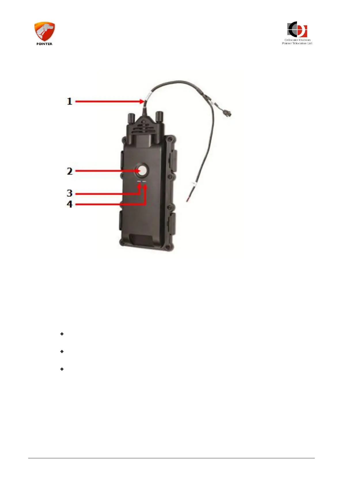
4.1.2 The CelloTrack Power Interface
1. CelloTrack Power harness (pigtail)
2. FB (Front Button)
3. COMM LED
4. SYS LED
4.1.3 CelloTrack Front Button and LEDs
The Front Button allows activation/de-activation, battery status check and battery
replacement sequence.
The SYS LED is a dual color (Green and Red) LED, which indicates unit
activation/de-activation, panic, and battery status/replacement.
The COMM LED is a dual color (Green and Red) LED, which indicates the unit’s
cellular communication and position status.
4.1.4 CelloTrack Connector
The CelloTrack 6-pin connector is protected by a plastic cover, providing IP67
compliancy. The following illustration shows the CelloTrack unit with the rubber cover
removed.