CelloTrack LTE Plus Overview
CelloTrack XT LTE Overview.docx Page 17 of 40
Copyright © 2020 by Pointer Telocation, Ltd.
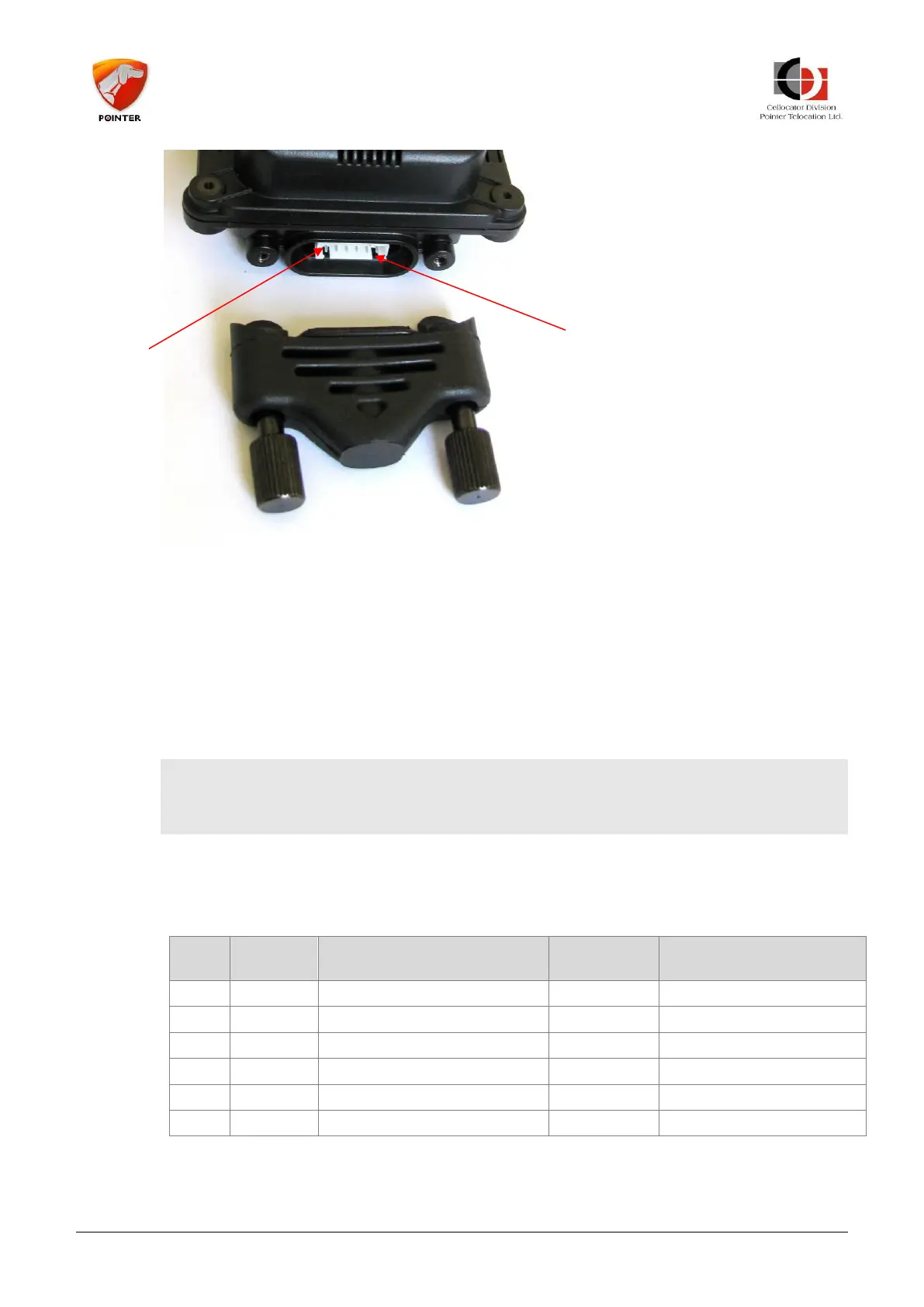
The connector pin out is as follows:
Pin 1 – VCC
Pin 2 – Ground (GND)
Pin 3 – General Purpose I/O 1 (GP1)
Pin 4 – General Purpose I/O 2 (GP2)
Pin 5 – RS232 TXD
Pin 6 – RS232 RXD
------------------------------------------------------------------------------------------------
NOTE: Removing the connector cover revokes the unit’s IP67 compliancy. It is the
customer’s responsibility to provide proper sealing if the connector cover is removed.
------------------------------------------------------------------------------------------------
4.1.5 CelloTrack Power Harness
The CelloTrack Power utilizes a 45 cm pigtail harness which ends with several free
wires and a connector for the programming cable, as described in the following table.
Programming
Connector Pin No.