It is necessary to clean the pool filter and pump
basket prior to the installation of the Polaris 140.
➜ After cleaning the pool filter, record the filter
pressure here for future reference: _____
psi. We recommend cleaning the pool filter
when the pressure is 5-10 psi above the
number recorded here.
B. Identifying the Type of Pool
Connection
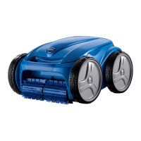
The Polaris 140 comes equipped to connect to a
dedicated suction line or a pool skimmer. We rec-
ommend the Polaris be installed to the dedicated
suction line if one is present.
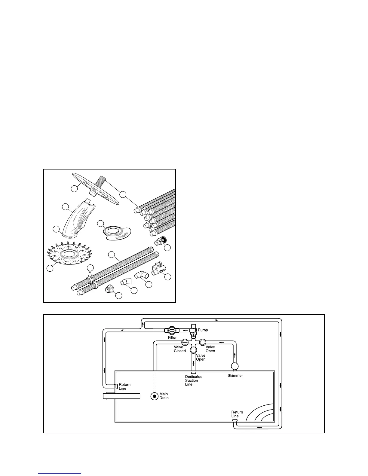
A dedicated suction line is a 1-1/4" to 2" suction
line, usually located between 6" to 12" below the
water's surface in the center of the longest pool
wall. If there is not one present, refer to Section D.
C. Installing in a Dedicated
Suction Line
1. Turn off the pool pump.
2. If the suction line opening is not covered
by a safety vacuum fitting, install the
universal adapter. If a safety fitting is
present, it is not necessary to install the
universal adapter.
➜ If your dedicated suction line does not have
a safety vacuum fitting, we recommend that
you contact your local Polaris dealer.
 Loading...