-11-
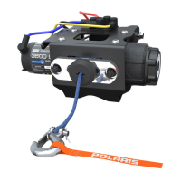
Figure 22
17. Connect the blue (PN 4013469), yellow
(PN 4013468), red (PN 4013471) and black wires
(PN 4013470) to the contactor terminals and put
the caps. Figure 21.
NOTE: Color coding for terminals will be on
contactor (PN 4013465).
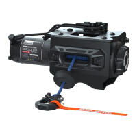
18. Hook up the negative (black) (PN 4013470) and
positive (red) (PN 4013471) terminals to the bus
bar. Figure 22.
Figure 21
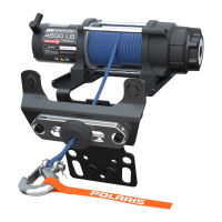
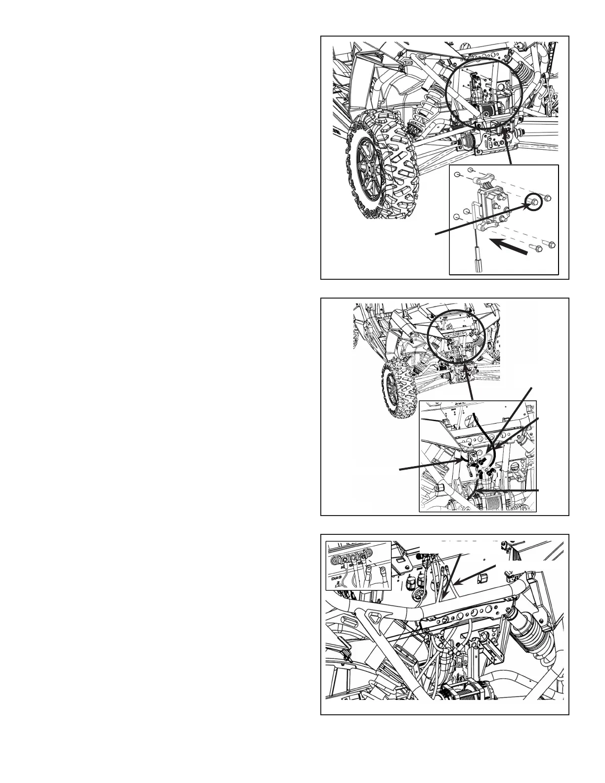
16. Mount the winch contactor (PN 4013465) on the
rewall with the four bolts (PN 7519330) at the
specied drilled holes. Figure 20.
NOTE: Ensure that the yellow color code on the
contactor is on top.
Figure 20
Positive Red
Negative Black
Black Wire
Blue
Wire
Red
Wire
Yellow
Wire
Bolt
 Loading...