-14-
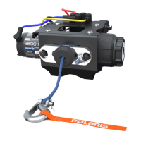
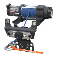
25. Route the cable from auto-stop control unit to the
socket wire connector (PN 4014228). Figure 29.
Figure 29
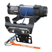
Figure 31
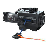
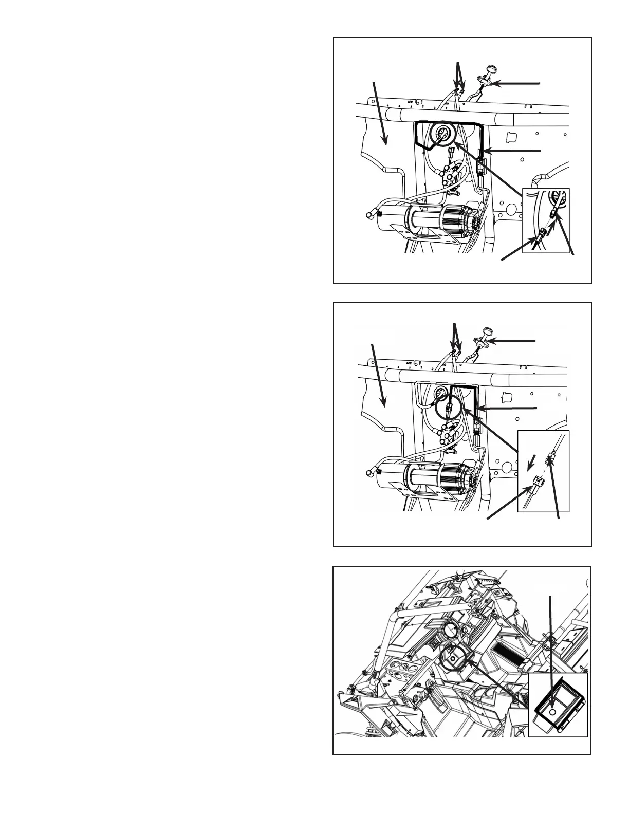
26. Route the cable (highlighted) from auto-stop control
unit to the contactor. Figure 30.
27. Cut out a hole in the din box for mounting the
socket (PN 4014228). Figure 31.
NOTE: Follow the instruction on the back of the din
for the cutout.
NOTE: Position may change as per requirement.
Socket
Winch
Hole
Firewall
Auto-stop
Control Unit
Contactor
Connector
Socket
Winch
Bus Bar
Firewall
Cable
Socket Wire
Connector
Cable
Bus Bar
Auto-stop
Control Unit
Figure 30
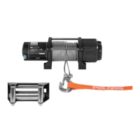
For 3500 and 4500 Winch Kits:
 Loading...